
Shielding method and shielding structure of radio frequency test circuit

A technology of radio frequency testing and shielding structure, applied in the direction of shielding devices, etc., can solve problems such as inconvenient circuit debugging, affecting debugging results, and differences in shielding environments, and achieve good electromagnetic shielding effects, improved shielding effects, and lower heights

Inactive Publication Date: 2013-05-01
THE 41ST INST OF CHINA ELECTRONICS TECH GRP
View PDF7 Cites 13 Cited by
  • Summary
  • Abstract
  • Description
  • Claims
  • Application Information

AI Technical Summary

Problems solved by technology

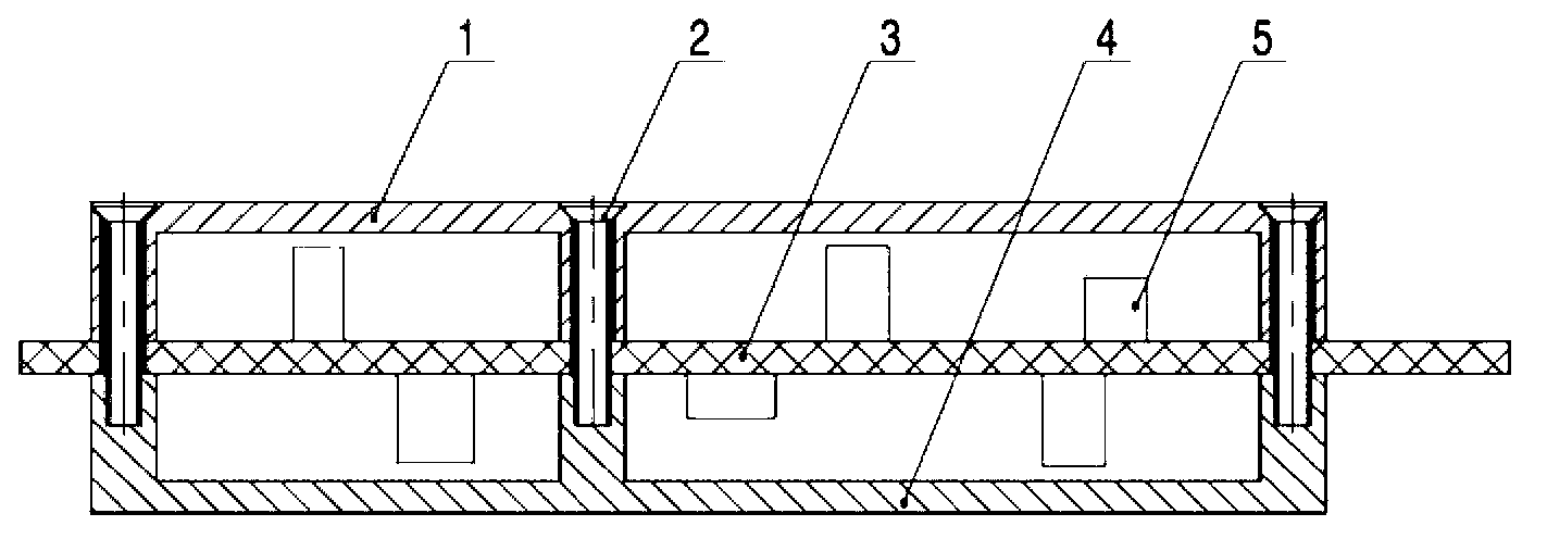
Although this shielding method can meet the requirements, it has the following disadvantages: the volume is too large, especially in the hand-held instrument with limited space; more mounting screws are required, in order to prevent the electromagnetic leakage of the gap, the distance between the screws is theoretically several mm; circuit debugging is inconvenient, the shielding box needs to be completely removed to expose the components, and due to the large difference from the shielding environment in the final use state, it will affect the debugging results.

Method used


Image

  • Shielding method and shielding structure of radio frequency test circuit
  • Shielding method and shielding structure of radio frequency test circuit
  • Shielding method and shielding structure of radio frequency test circuit

Examples


Embodiment Construction

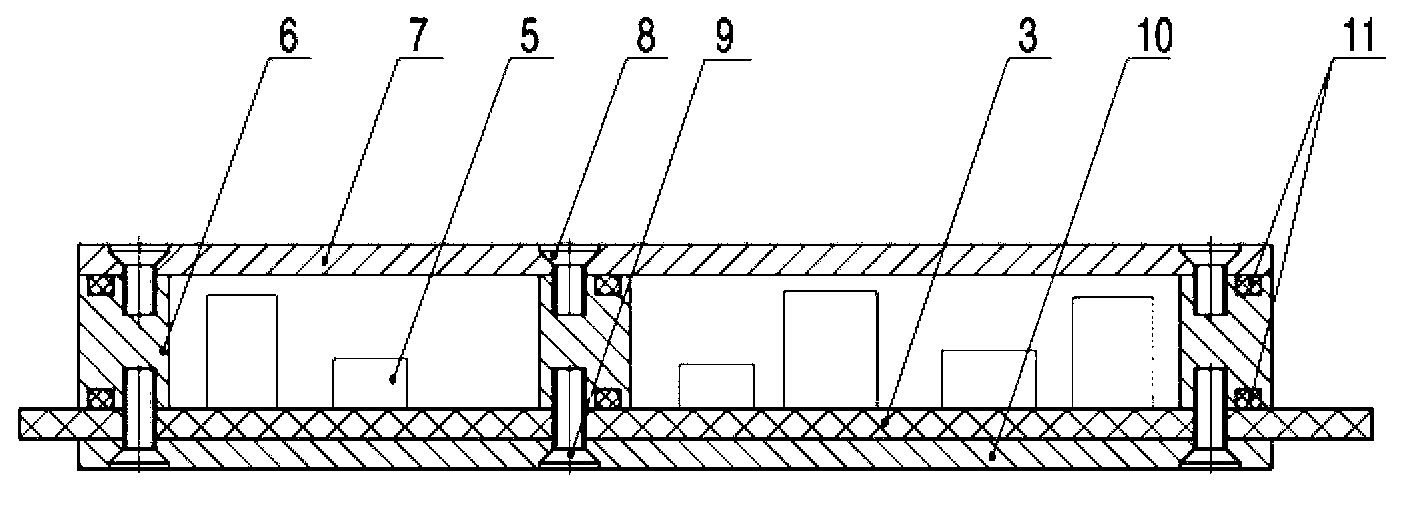
[0026] combine figure 2 , image 3 , illustrating the steps that the shielding method of the radio frequency test circuit of the present invention adopts:

[0027] First of all, when designing the circuit board 3, all components 5 are arranged on one side by means of small devices and compact arrangements; circuits with different functions and different powers are divided into layouts, and wide ground wires are used for isolation to prevent signal coupling.

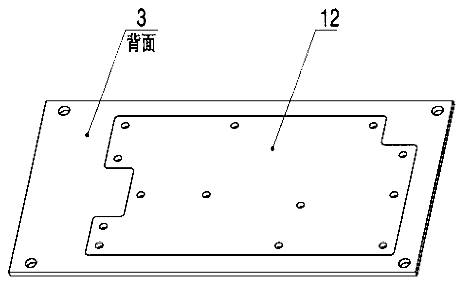
[0028] Secondly, the back of the circuit board 3 is designed with blind holes without any wire holes to reduce electromagnetic interference; the back is set as a solid copper-skin ground plane 12, which is gold-plated to improve conductivity.

[0029] Again, after the components and parts 5 on the circuit board 3 are assembled, the circuit board 3 is installed on the shielding frame 6

[0030] and shielding plate 10. Fix with screw 9 and seal with conductive rubber strip 11.

[0031] Finally, after the circuit debugg...


PUM


Abstract

The invention discloses a shielding method and a shielding structure of a radio frequency test circuit. The shielding method comprises the following steps that a circuit board is provided with a timing single-side arrangement device and a partition layout circuit; the back side of the circuit board adopts the blind hole design, and a whole block of gold-plated copper sheet is solidly connected with the ground; the upper side and the lower side of the circuit board are respectively provided with a metal shielding cover, the shielding cover at the side of the device is provided with a movable upper cover, and the debugging is convenient; after the circuit is debugged, the movable upper cover is installed, and the device is sealed; and the shielding structure comprises a shielding box, the shielding box consists of a shielding cover, a shielding frame and a shielding board, the circuit board is arranged between the shielding frame and the shielding plate, the circuit board, the shielding frame and the shielding plate are tightly connected through screws, the shielding cover and the shielding frame are independently connected, and the shielding frame, the shielding cover and the circuit board are sealed through striped elastic conducting materials. Measures are adopted in two aspects including the circuit design and the structure design, and the goals of simple structure, small size, convenience in installation and debugging and good electromagnetic shielding effect are reached.

Description

technical field [0001] The invention relates to the field of electronic measurement, in particular to a shielding method and a shielding structure of a radio frequency test circuit. Background technique [0002] Radio frequency test circuit is an important part of the modern electronic measurement field and has a wide range of applications. Due to its high operating frequency, the electromagnetic radiation generated has greater interference to sensitive circuits; due to the coupling effect, there is also more interference between circuits. In order to improve the anti-interference ability of the circuit, circuits with different functions and different powers are usually arranged in partitions when designing the circuit, and are isolated with wider grounding lines to prevent signal coupling. In order to enhance the isolation effect, each key circuit is shielded with a metal shielding box. [0003] Common RF test circuits, the shielding solutions such as figure 1 As shown:...

Claims


Application Information

Patent Timeline
Patent Type & Authority Applications(China)
IPC IPC(8): G01R1/18
Inventor 张杰王安意
Owner THE 41ST INST OF CHINA ELECTRONICS TECH GRP
Learn More