
Joint locking assembly and method

A technology for locking components and components, which is applied in the direction of connecting components, connections, rods, etc., and can solve problems such as difficult automatic locking and large volume

Inactive Publication Date: 2013-04-24
STUDIO MODERNA SA
View PDF4 Cites 6 Cited by
  • Summary
  • Abstract
  • Description
  • Claims
  • Application Information

AI Technical Summary

Problems solved by technology

While this construction may be suitable for heavier linkages, it has the disadvantage of being bulky and not readily facilitating automatic locking

Method used


Image

  • Joint locking assembly and method
  • Joint locking assembly and method
  • Joint locking assembly and method

Examples


Embodiment Construction

[0093] In the following paragraphs, examples of the invention will be described in detail, by way of example, with reference to the accompanying drawings, which are not drawn to scale and the parts shown are not necessarily to scale with each other. Throughout the specification, the illustrated embodiments and examples should be considered as exemplifications of the invention, not as limitations of the invention. As used herein, "the present invention" refers to any one of the embodiments of the invention described herein, and any equivalents. Furthermore, reference herein to aspects of the invention does not imply that all claimed embodiments or methods must include the referenced aspects.

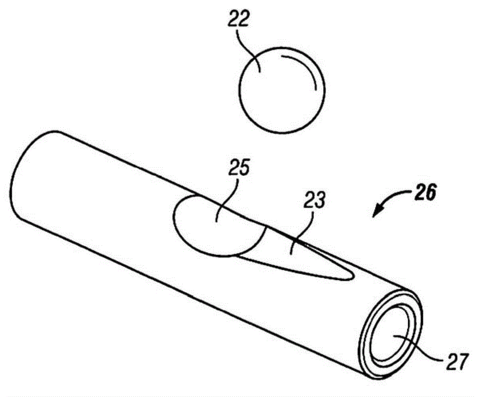
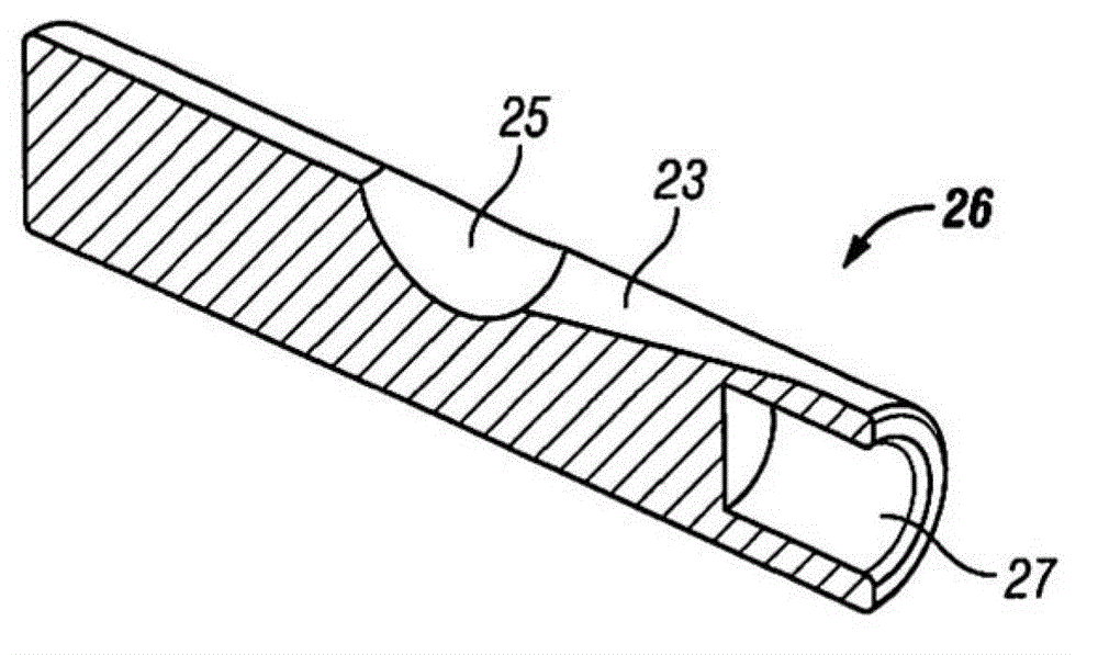
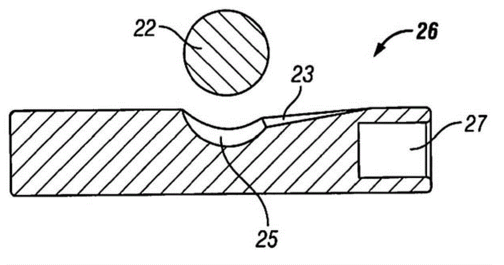
[0094] see Figure 1 to Figure 10 An exemplary embodiment of the engagement locking assembly includes one or more button members 26 which are substantially rod-shaped members sized to be placed within other engagement components to facilitate folding and locking of the mechanical compone...


PUM


Abstract

A system of folding mechanical components comprises a bearing ball, a stationary body defining at least one concave recess sized to receive at least a portion of the bearing ball, a rotatable body rotatably coupled to the stationary body and one or more button members. The rotatable body defines two channels therein, and one or more button members are sized to be disposed in the channels. Each button member defines a recess with a rounded concave portion sized to receive at least a portion of the bearing ball. In a locked position the bearing ball contacts the sloped recesses of the button members and has limited contact with the concave recess of the stationary body. In an unlocked position the bearing ball contacts the rounded concave portions of the button members and has relatively more contact with the concave recess of the stationary body.

Description

[0001] Cross References to Related Applications [0002] This application has priority to U.S. Application Serial No. 61 / 358,382, filed June 24, 2010, entitled "Joint Locking Assembly and Method," which is not a provisional application of the above-mentioned U.S. application, the entire contents of which are hereby incorporated by reference In this application. technical field [0003] The present invention relates to joint locking assemblies and methods for locking and folding mechanical components. Background technique [0004] Joint locking assemblies are employed in many different devices to lock joint elements, usually in a fixed relationship. The use of engagement components may be used to enable folding of the device, thereby reducing the area occupied by the device eg for storage or transport purposes. In such mechanisms, the mechanical parts to be folded are joined together at joints which, in use, are securely secured or locked, but which are releasable in prepa...

Claims


Application Information

Patent Timeline
Patent Type & Authority Applications(China)
IPC IPC(8): B62K15/00B62K19/18F16B7/04F16L37/23
CPCB62K2015/001B62K15/006B62K15/00F16B7/042B62K19/18F16L37/23B62K2206/00F16B7/04B62K15/008Y10T403/32418
Inventor 兹登科·萨夫塞科爱丽斯·沃泽里
Owner STUDIO MODERNA SA
Learn More