Time of exposure non-intervention measuring device and method of X-ray machine

A technology of exposure time and measurement device, which is applied in X-ray equipment, electrical components, etc., can solve the problems of exposure time measurement error, large constant between amplifying circuits, and slow change of ray radiation rate, so as to reduce errors and influence Effect

Inactive Publication Date: 2013-04-24
刘志宏
View PDF6 Cites 4 Cited by
  • Summary
  • Abstract
  • Description
  • Claims
  • Application Information

AI Technical Summary

Problems solved by technology

[0007] At present, for the non-interventional measurement of the exposure time of X-ray machines, the combination of scintillator and semiconductor photodiode is generally used as the radiation detector. The junction capacitance of the photodiode and the interval constant of the amplifier circuit connected to it are relatively large, so it is impossible to measure the scintillation. Each scintillation signal generated by the scintillator forms a linear pulse signal output, that is, an integral effect is formed on the narrow pulse width signal, and multiple scintillation signals generated by the scintillator are accumulated (integrated) by the detector and the electronic circuit to form an output current (or voltage), The entire measurement circuit works when the output voltage is proportional to the incident dose rate, and the exposure time is calculated by measuring the change of the output voltage, precisely because the response time of the entire measurement circuit is long, and the front and rear edges of the voltage change are higher than the incident ray radiation. The rate changes slowly, so it brings a certain measurement error to the calculated exposure time

Method used


Image

  • Time of exposure non-intervention measuring device and method of X-ray machine
  • Time of exposure non-intervention measuring device and method of X-ray machine
  • Time of exposure non-intervention measuring device and method of X-ray machine

Examples


Embodiment 1

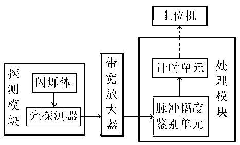
[0033] Such as figure 1 , X-ray machine exposure time non-interventional measurement device, including a detection module and a processing module, the detection module includes a scintillator and a photodetector, the scintillator is located in the ray radiation area of ​​the X-ray machine, and the photodetector The detection end is close to the scintillator, and its output is connected to the processing module through a bandwidth amplifier. The processing module includes a pulse amplitude discrimination unit and a timing unit. The input of the pulse amplitude discrimination unit is connected to the output of the bandwidth amplifier, and its output connected to the timing unit.

[0034] The scintillator used in this example is a lanthanum bromide crystal (LBC) scintillator doped with cerium chloride. The lanthanum bromide scintillator converts incident rays into optical signals. The light output is 1.3~1.6 times of NaI:TI crystal, the decay time is 1 / 20~1 / 10 of NaI:TI crystal,...

Embodiment 2

[0043] The structure of this embodiment is basically the same as [Example 1], the difference is that the number of counters in the timing unit is 4, and the structure diagram of the timing unit is as follows Figure 7 shown.

[0044] In this embodiment, after the number of counters is increased to 4, the upper limit of the continuous pulse rate of the timing unit is increased.

[0045] The measurement process of this embodiment is basically the same as [Example 1]. When measuring the time interval, four counters are used to measure in turn. When a certain count cannot be counted during the stop / read / reset operation, the pulse The signal can be counted sequentially by the other three counters, thus increasing the upper limit of the continuous pulse rate of the timing unit.

Embodiment 3

[0047] The structure of this embodiment is basically the same as [Embodiment 1]. The difference is that the hardware of the processing module in this embodiment is different, and the analog signal is represented by a data stream, such as Figure 8 As shown, the pulse amplitude identification unit includes an FPGA, and the FPGA is connected to the output of the bandwidth amplifier through an A / D converter, and the A / D converter converts the output voltage signal of the bandwidth amplifier into a digital signal to form a continuous data stream and then transmits it to the FPGA. The size of the data in the stream represents the amplitude of the signal. The FPGA adopts the chip of XC5VSX95T, which is the model of Xilinx. This chip can provide various data preprocessing functions. In this embodiment, XC5VSX95T mainly provides the pulse amplitude identification function, and also uses two comparators , that is: the amplitude of the received data stream below V LT The following is set ...


PUM


Abstract

The invention discloses a time of exposure non-intervention measuring device and a method of an X-ray machine. The time of exposure non-intervention measuring device comprises a detecting module and a processing module. The detecting module comprises a flickering body and a light probing device. A probing end of the light probing device is tightly adhered to the flickering body and an output end of the light probing device is connected with the processing module through a bandwidth amplifier. The time of exposure non-intervention measuring device and the method of the X-ray machine have the advantages that the defect of fake 'time of exposure' which might occur in an intervention measuring manner is overcome, a time interval of every two ray impulses is constantly measured by the short fluorescence fall time flickering body, the light probing device, the bandwidth amplifier and the high-speed data real-time processing module, so that the method of measuring density of nuclear incidents is achieved, affection of response time of an electronic circuit on a leading-edge and a lagging-edge of density variation of the nuclear incidents is reduced and an error in working out the time of exposure is narrowed.

Description

technical field [0001] The invention relates to a measuring device and a method for measuring the exposure time of an X-ray machine, in particular to a device and a method for non-intervention measurement of the exposure time of an X-ray machine. Background technique [0002] The measurement of the exposure time of the X-ray machine is often used in the image quality control of the hospital and the quality control of the operation of the technical supervision department. [0003] The exposure time of the X-ray machine is defined as: Exposure time (Irradiation Time) - the duration of exposure of the X-ray machine measured according to the prescribed method, usually the time when the radiation dose rate exceeds a certain level. [0004] The loading time of the X-ray machine is defined as: Loading Time—the time when the anode input power is applied to the X-ray tube measured by the specified method. Usually refers to the time interval from when the X-ray tube voltage first ris...

Claims


Application Information

Patent Timeline
IPC IPC(8): H05G1/28
Inventor 刘志宏
Owner 刘志宏
Why Eureka
Try Eureka