
Split screw pile and welding method thereof

A spiral ground pile and split-type technology, applied in welding equipment, welding accessories, sheet pile walls, etc., can solve the problems of deterioration of welding seam crystallization conditions, poor weld pool formation and metal bonding, and small effective welding area. The effect of reducing processing and production costs, eliminating unfused defects between layers, and increasing effective welding area

Active Publication Date: 2013-04-24
POWERWAY RENEWABLE ENERGY
View PDF10 Cites 9 Cited by
  • Summary
  • Abstract
  • Description
  • Claims
  • Application Information

AI Technical Summary

Problems solved by technology

However, since the groove form of conventional welded joints is generally V-shaped or U-shaped grooves, both the pile body and the pile tip need to be grooved, which has troublesome processing and butt joints, small effective welding area, poor weld strength and Disadvantages of low welding efficiency
At the same time, 12Cr1MoV steel is a pearlitic heat-resistant steel. Due to the high carbon content and alloy elements, hardened structures are prone to appear in welds and heat-affected zones, which reduces plasticity and toughness, and poor weldability. When the stress is large, it is easy to crack
Since the chemical composition of 12Cr1MoV steel and Q235B carbon steel is very different, their welding belongs to the welding of dissimilar steels. To obtain reliable welded joints under fusion welding conditions, there are many problems: 1. Due to the thermal conductivity and The difference in specific heat capacity makes the melting of the two out of sync, poor formation of molten pool and metal bonding, resulting in poor weld crystallization conditions, poor weld performance and form
2. The linear expansion coefficients of the two are different, resulting in different shrinkages on both sides of the weld during the cooling process after forming the welded connection, resulting in a complex high-stress state in the welded joint, which in turn accelerates the generation of cracks
3. There are problems of weld dilution and transition layer formation
[0005] In summary, it can be seen that the welding of these two dissimilar steels using the traditional welded joint structure and welding process cannot achieve effective welding between the two dissimilar steels, so it is necessary to improve the structure and welding process of the welded joint

Method used


Image

  • Split screw pile and welding method thereof
  • Split screw pile and welding method thereof
  • Split screw pile and welding method thereof

Examples


specific Embodiment

[0038] Hereinafter, the present invention will be further described with reference to the drawings and specific implementations:

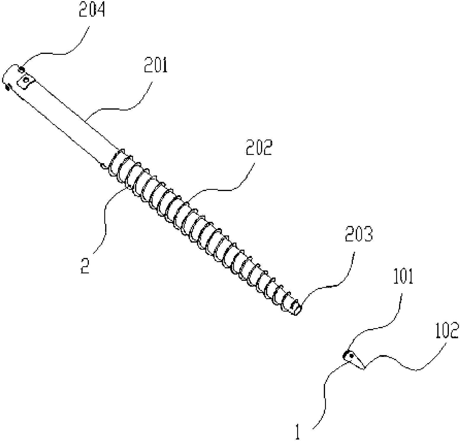
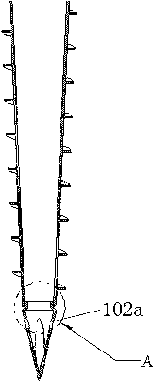
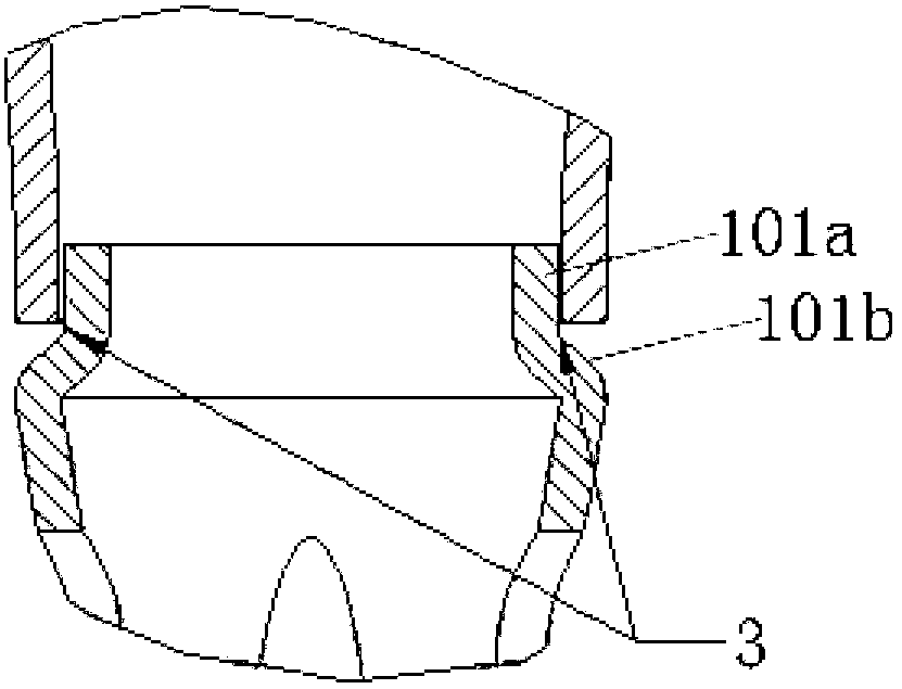
[0039] Reference Figure 1-Figure 3 , The split spiral ground pile described in this embodiment includes a split tubular pile body 2 and a conical ground drilling tip 1. The outer surface of the pipe body 201 of the pile body 2 is sheathed in a spiral belt shape The helical blade 202 of the body; the ground-boring tip 1 includes a tip portion 102 and a truncated cone-shaped tail 101; the truncated cone-shaped tail 101 includes an insertion portion 101a that matches the inner wall of the pile body 2 and a diameter larger than the insertion portion The inclined surface 101b; the insertion portion 101a of the drill tip is inserted into the socket hole of the pile 2, so that the inclined surface 101b of the drill tip 1 and the open end surface 203 of the pile 2 form an annular weld Groove 3, the axial cross-section of the annular welding groove 3 is a ri...


PUM

PropertyMeasurementUnit
areaaaaaaaaaaa
breaking strengthaaaaaaaaaa

Abstract

The invention discloses a split screw pile and a welding method thereof. The split screw pile comprises a pile body and a submerging tip, which are split. The submerging tip comprises a sharp end and a truncated-cone-shaped tail. An insert part of the submerging tip is inserted into a socket hole of the pile body so that a circular welding groove is formed between a slant part of the submerging tip and an open end of the pile body. The pile body is welded to the circular welding groove of the submerging tip to form an integrated structure. The welding method of the split screw pile includes the steps of firstly, performing connector butt welding; secondly, cleaning before welding; thirdly, preheating; fourthly, welding, namely performing manual gas tungsten arc welding to complete bottoming by nickel-base welding wires ERNiCrMo-3, and performing manual arc welding to complete filling and capping; and fifthly, thermally treating after welding. Therefore, the effective welding between the Q235B pile body and the 12Cr1MoV submerging tip is achieved, butt joint of connectors is simple and reliable, operating efficiency is improved, effective welding area is increased, weld strength is increased and processing and production costs are lowered.

Description

Technical field [0001] The invention relates to a screw ground pile, in particular to a split type screw ground pile and a welding method thereof. [0002] Background technique [0003] The application range of piles in engineering construction is relatively large, and they are widely used in construction industries such as solar photovoltaic and wind energy. Ground piles are the main connection structure commonly used in the construction and steel structure industries to connect to the ground. The existing spiral ground piles all adopt an integrated structure, the pile body is a tubular structure, the periphery of the pile body is connected with spiral blades, and the front end of the pile body is a pointed structure. The entire spiral pile can only be applied to soil with a single characteristic. When it encounters soil with other characteristics, this type of spiral pile loses its use value. On the one hand, it limits the scope of use of ground piles. On the other hand, when e...

Claims


Application Information

Patent Timeline
Patent Type & Authority Applications(China)
IPC IPC(8): E02D5/56E02D5/72B23K9/00B23K9/32B23K9/167
CPCB23K9/00E02D5/56E02D5/72B23K9/32B23K9/028B23K9/167B23K33/006
Inventor 吴克耀
Owner POWERWAY RENEWABLE ENERGY
Learn More