
Airtightness packaging radiating structure of integrated circuit

A technology of integrated circuits and heat dissipation structures, applied in circuits, electrical components, electrical solid devices, etc., can solve problems such as electrical performance degradation, excessive chip temperature rise, and functional failure, and achieve excellent air tightness

Inactive Publication Date: 2013-04-03
58TH RES INST OF CETC
View PDF4 Cites 7 Cited by
  • Summary
  • Abstract
  • Description
  • Claims
  • Application Information

AI Technical Summary

Problems solved by technology

[0002] The semiconductor integrated circuit chip is welded upside down on the pad / bump of the shell or the substrate. For circuits with large power consumption, it is not enough to dissipate heat only through the heat conduction of the shell or the substrate, and to dissipate heat from the chip to the surrounding air convection and radiation. The airtightness of the structure and high power density integrated circuits often lead to excessive temperature rise of the chip, resulting in a decrease in electrical performance or even functional failure

Method used


Image

  • Airtightness packaging radiating structure of integrated circuit
  • Airtightness packaging radiating structure of integrated circuit
  • Airtightness packaging radiating structure of integrated circuit

Examples


Embodiment Construction

[0014] The present invention will be further described below in conjunction with drawings and embodiments.

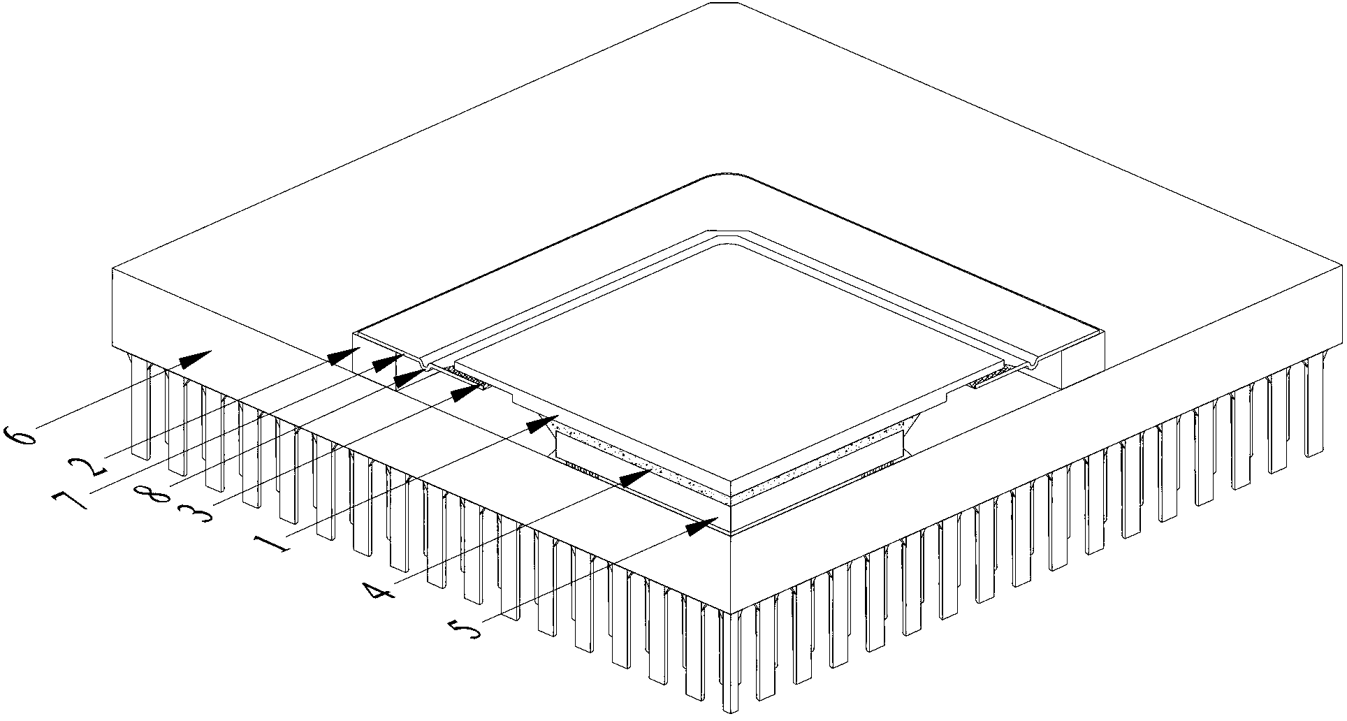
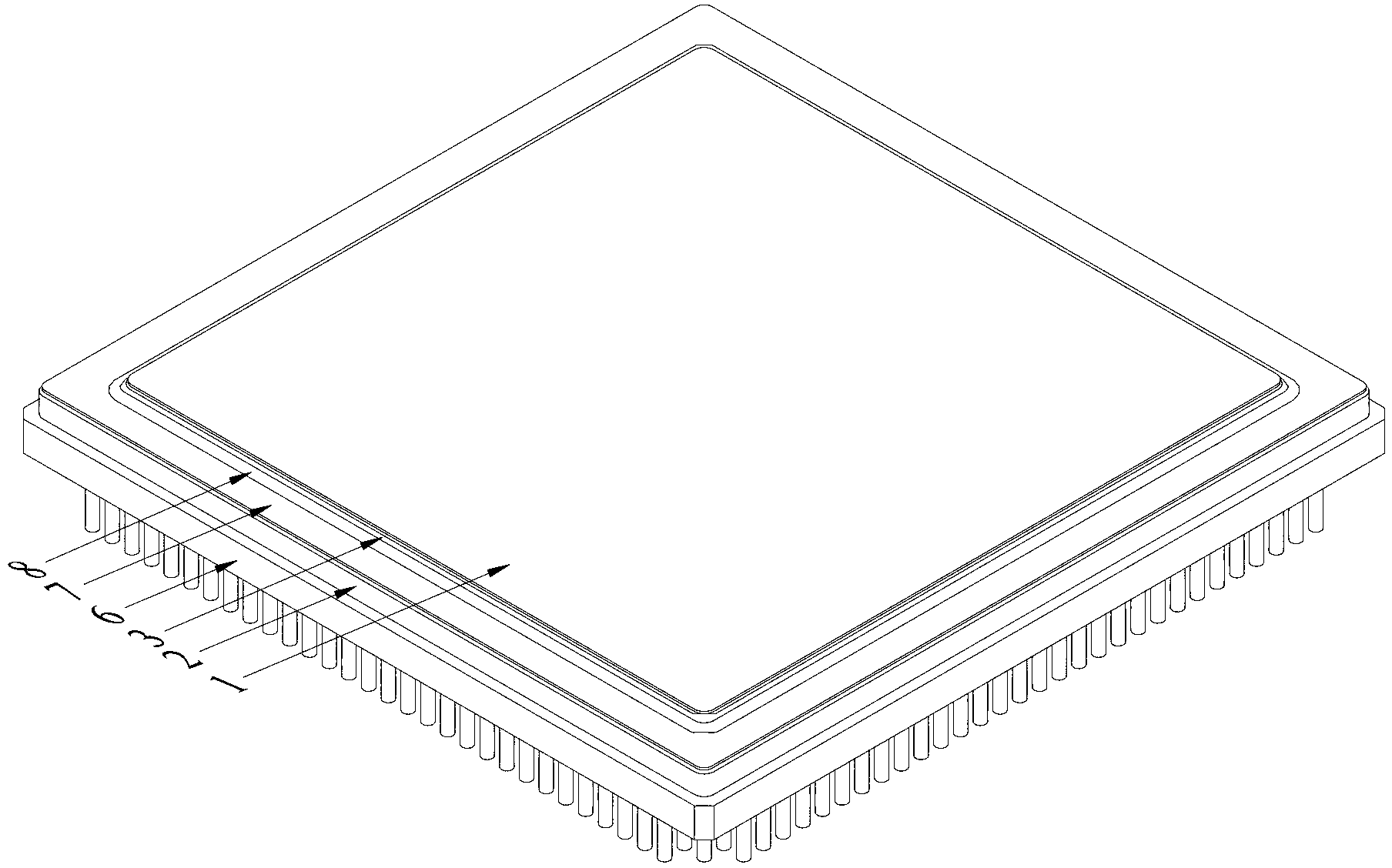
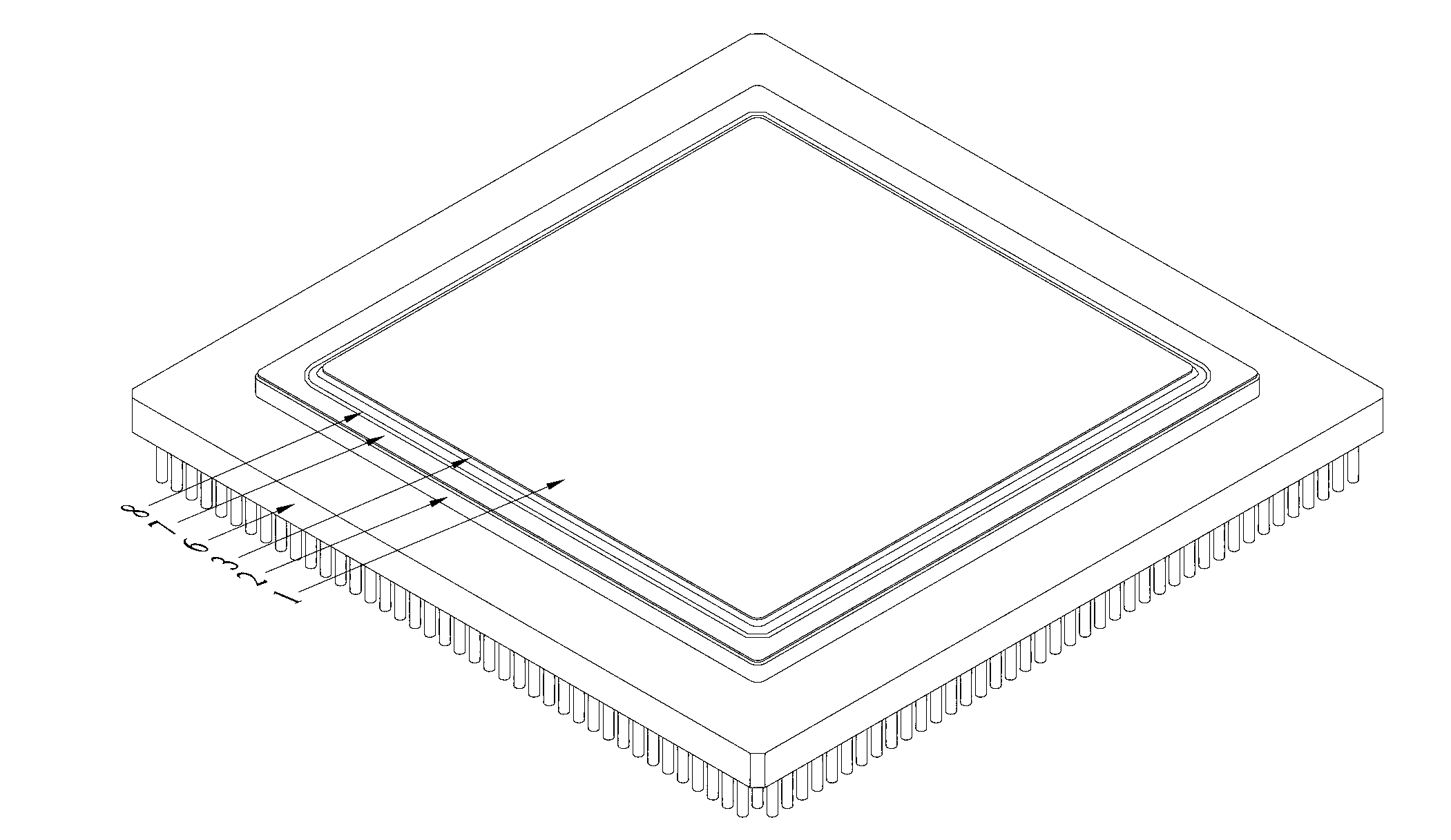
[0015] Such as figure 1 As shown, the heat dissipation structure of the present invention adopts a high thermal conductivity metal heat sink 1 that matches the thermal expansion base of the shell / substrate, and is brazed together with a welding frame 7 made of materials such as Kovar through brazing material 3; the heat sink 1 Weld together with soft solder 4 and metallized upside-down soldering chips 5; finally weld the welding frame 7 and the sealing ring 2 on the shell or substrate 6 together by laser welding, parallel seam welding, etc. to form an airtight The heat sink 1 can efficiently conduct the heat of the chip to the cold plate, etc., forming an excellent thermal channel. A circle of grooves can be set on the welding frame 2 to form a buffer ring 8 around the heat sink 1 .

[0016] In the integrated circuit airtight heat dissipation structure of the present ...


PUM


Abstract

The invention relates to an airtightness packaging radiating structure of an integrated circuit. The airtightness packaging radiating structure comprises a casing or a base plate and a back-off welding chip, wherein the back-off welding chip is welded with a heat sink through slicken solder, a round of the heat sink is welded with a welding frame through solder in brazing mode; and then the welding frame is welded with the casing or a sealing ring on the base plate to form airtightness packaging. A round of groove is arranged on the welding frame to form a buffer ring which surrounds the heat sink for a round. The airtightness packaging radiating structure has the advantages that the existing packaging structures and materials are not changed, and by utilizing the existing assembling welding device and technology, packaging airtightness can be achieved, and the problems of radiating of back-off welding (FC) can be solved.

Description

technical field [0001] The invention relates to an integrated circuit package structure, in particular to a heat dissipation structure for a flip-bonded (FC) chip packaged in an airtight and highly reliable ceramic package, and belongs to the technical field of electronic manufacturing. Background technique [0002] The semiconductor integrated circuit chip is welded upside down on the pad / bump of the shell or the substrate. For circuits with large power consumption, it is not enough to dissipate heat only through the heat conduction of the shell or the substrate, and to dissipate heat from the chip to the surrounding air convection and radiation. The airtight and high power density integrated circuit of the structure often leads to excessive temperature rise of the chip, which leads to a decrease in electrical performance or even functional failure. Contents of the invention [0003] The purpose of the present invention is to overcome the deficiencies in the prior art, so...

Claims


Application Information

Patent Timeline
Patent Type & Authority Applications(China)
IPC IPC(8): H01L23/367H01L23/31
Inventor 丁荣峥李欣燕高娜燕
Owner 58TH RES INST OF CETC
Learn More