Low-water-sucking water pump

A low water absorption and water pump technology, applied in the direction of pumps, pump devices, pump components, etc., can solve the problems of reduced service life, inability to pump water, and easy burnout of the motor, so as to improve the service life, ensure safety, and improve the utilization rate. Effect

Active Publication Date: 2013-04-03
宁波君禾智能科技有限公司
View PDF7 Cites 7 Cited by
  • Summary
  • Abstract
  • Description
  • Claims
  • Application Information

AI Technical Summary

Problems solved by technology

After the pump is turned on, the impeller rotates at a high speed, and the liquid in it rotates with the blades. Under the action of centrifugal force, it flies away from the impeller and shoots out. The speed of the injected liquid gradually slows down in the diffusion chamber of the pump casing, and the pressure gradually increases. The outlet is discharged, and a vacuum low-pressure area without air and liquid is formed at the center of the blade because the liquid is thrown to the surroundings. The liquid in the liquid pool flows into the pump through the suction pipe under the action of the atmospheric pressure on the pool surface, and the liquid is continuous like this It is continuously sucked up from the liquid pool and continuously flows out from the pump outlet, but the motor and the impeller in the current submersible pump are all in the same space, making the space of the pump chamber relatively large. When low water level pumping is required, it is difficult to quickly remove the air in the pump chamber, so it is difficult to establish a continuous suction effect when the water level is low, so it is impossible to pump water at a water level of about 5mm, which makes the pumping efficiency low. Restrictions, and the motor is cooled by water during work. If there is no circulating water to cool the motor, the motor will heat up quickly, so the motor is easy to burn out, reducing the overall service life, so it needs to be improved

Method used


Image

  • Low-water-sucking water pump
  • Low-water-sucking water pump
  • Low-water-sucking water pump

Examples


Embodiment 1

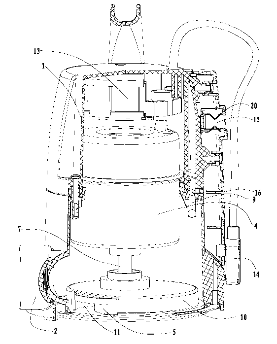
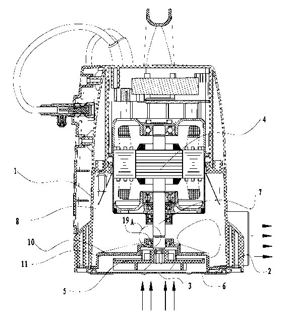
[0024] Such as figure 1 , figure 2 , image 3 As shown, the low-suction water pump provided by the present invention includes a pump casing 1, a first water outlet 2, a water inlet 3, a motor 4 and an impeller 5, and the first water outlet 2 is arranged on one side of the pump casing 1, and the The impeller 5 is fixed on the rotating shaft 7 of the motor 4, and a base 6 is fixed on the bottom of the pump housing 1, and the base 6 and the pump housing 1 form a pump chamber 8, and the motor 4 and the impeller 5 are placed in the pump chamber 8, an exhaust valve device 9 with a steel ball is provided on the pump casing 1, the water inlet 3 is provided on the base 6 below the position of the impeller 5, and a shroud 10 is provided on the upper part of the impeller 5, Such as Figure 4 Said, the wind deflector 10 passes through the rotating shaft 7 and achieves a sealing arrangement with the rotating shaft 7 through a sealing ring 19, and the wind deflector 10 and the base 6 fo...

Embodiment 2

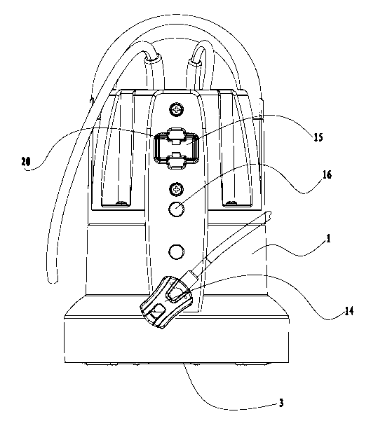
[0027] Such as Figure 5 As shown, the general structure of this embodiment is the same as that of Embodiment 1, except that a controller 13 is provided above the motor 4 in the pump chamber 8, and a water level sensor 14 is provided on the pump casing 1. The water level sensing head 14 is electrically connected with the controller 13; on the side of the pump housing 1, an induction head socket 15 and three induction head positioning jacks 16 capable of cooperating with the water level induction head 14 are respectively provided, and the induction head socket 15 A stainless steel sheet 20 for short-circuiting the sensing head is arranged inside, and the positioning jack 16 of the sensing head can be determined according to the requirements of specific embodiments.

[0028] When the water pump needs to be manually operated during work, the water level sensor head 14 can be inserted into the sensor head socket 15 to realize the manual control of the water pump startup function...

Embodiment 3

[0030] Such as Figure 6 , Figure 7 As shown, the general structure of this embodiment is the same as that of Embodiment 2, the difference is: in order to enable the water flow to be quickly thrown out from the nozzle 10, the inner wall of the nozzle 10 is provided with a first vortex groove 17 The opening at one end of the first vortex groove 17 corresponds to the water inlet 3 to form a volute, and the opening at the other end of the first vortex groove 17 is the second water outlet 12, which is smaller than the diameter of the opening at one end corresponding to the water inlet 3 and the diameter of the second water outlet. The other end corresponding to the second water outlet 12 mentioned above is open.


PUM


Abstract

The invention discloses a low-water-sucking water pump, which comprises a pump shell, a first water outlet, a water inlet, a motor and an impeller, wherein the first water outlet is arranged on one side of the pump shell; the impeller is fixedly arranged on the spindle of the motor; the bottom of the pump shell is fixedly provided with a base; a pump cavity is formed by the base and the pump shell; the motor and the impeller are both arranged in the pump cavity; the pump shell is provided with a vent valve device with a steel ball; the water inlet is arranged on the position relatively below the impeller on the base; the upper part of the impeller is provided with a fairing; the fairing passes through the spindle and is in sealing with the spindle by a sealing ring; an inner cavity is formed by the fairing and the base; and the fairing is provided with a second water outlet from which conveying liquid can freely enter and leave. The invention aims to provide the low-water-sucking water pump which has the characteristics of high pumping speed, good effect and long service life, can be automatically started and quickly pumped, can be used for pumping or dewatering water pools, basements or other occasions with the lower water level.

Description

technical field [0001] The invention relates to a submersible pump, in particular to a low water suction pump. Background technique [0002] The submersible pump is a widely used water treatment tool in daily life. The shadow of the submersible pump can be seen in both agricultural production and industrial processing. The difference from ordinary water pumps is that it works underwater. When used, the whole The unit dives into the water and extracts groundwater to the surface. It is an indispensable tool in domestic water, mine rescue, industrial cooling, farmland irrigation, seawater lifting, ship load adjustment and fountain landscape. Before starting the pump, the suction pipe and the pump must be full liquid. After the pump is turned on, the impeller rotates at a high speed, and the liquid in it rotates with the blades. Under the action of centrifugal force, it flies away from the impeller and shoots out. The speed of the injected liquid gradually slows down in the dif...

Claims


Application Information

Patent Timeline
IPC IPC(8): F04D13/08F04D29/44
Inventor 张君波
Owner 宁波君禾智能科技有限公司
Why Eureka
Try Eureka