Indexable cutting insert for rough machining

A cutting blade and indexing technology, which is applied in the field of indexable cutting blades, can solve the problems of high transverse bending stiffness, increased blade wear, and increased blade cutting resistance, so as to enhance impact resistance, improve cutting performance, and reduce cutting The effect of resistance

Active Publication Date: 2015-01-21
OKE PRECISION CUTTING TOOLS CO LTD
View PDF5 Cites 0 Cited by
  • Summary
  • Abstract
  • Description
  • Claims
  • Application Information

AI Technical Summary

Problems solved by technology

Among the various design elements, the rake angle formed by the reference plane of the insert and the rake face is a key parameter. If the rake angle is too large, the cutting performance is good, but the cutting edge is easy to break, so wide chamfering or reduced cutting edge is often used for the cutting edge. The rake angle structure ensures strength, but this method of simple chamfering directly on the cutting edge can improve the impact resistance of the blade, but it will sharply increase the cutting resistance suffered by the blade and aggravate the wear of the blade
[0003] On the other hand, the chip breaking function design is also very important in the rough machining insert geometry design. Due to the large cutting depth and high lateral bending stiffness in rough machining, generally long and thick spiral chips will not be formed, and most of them are C-shaped chips. Mainly, its main chip breaking function is completed by the cutting unit of the tool tip. In the existing technology, the chip breaking groove of the tool tip cutting unit adopts plane transition more often, which is not conducive to the chip breaking of rough machining chips.

Method used


Image

  • Indexable cutting insert for rough machining
  • Indexable cutting insert for rough machining
  • Indexable cutting insert for rough machining

Examples


Embodiment 1

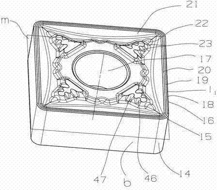
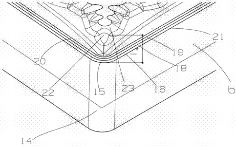
[0028] An indexable double-sided cutting insert, the insert body is a symmetrical square body up and down, such as Figure 1 to Figure 5 As shown, it includes two end surfaces and side surfaces, and four connection surfaces are arranged on the end surface, and the blade is positioned on the tool connection surface through the connection surfaces, specifically, fixed through the installation through hole 17 located at the geometric center of the blade body by a fixing screw . The two end faces of the blade body are arranged symmetrically with the middle section as the reference plane m, and the two adjacent side faces are connected by the arc surface 14; the eight cutting units are distributed at the angle between the two adjacent side faces of the upper and lower end faces, so that The cutting unit includes: the main cutting edge 15 formed by the intersection of the end surface and the arc surface 14, the intersection of the end surface and the side surface is a minor cutting ...


PUM


Abstract

The invention discloses an indexable cutting insert for rough machining. An insert body is a polygonal body, the geometrical center is provided with a mounting through hole, a chip breaker body is arranged around the mounting through hole, and cutting units are respectively distributed at the included angle between each two neighboring sides. The indexable cutting insert is characterized in that each cutting unit consists of a main cutting edge and an auxiliary cutting edge; each of the main cutting edge and the auxiliary cutting edge is provided with a chamfer plane and an arris plane, and a first front insert face and a second front insert face are connected with the chip breaker body through concave bottoms; at each cutting unit, the chip breaker body is provided with a boss, the surface of the boss gradually rises to form a first chip breaker and a second chip breaker, a first concave is formed between the ridge of the first chip breaker and the ridge of the second chip breaker, a second concave is formed between the second chip breaker and the chip breaker body, and both the first concaves and the second concaves are smoothly connected with the concave bottoms. Under the premise of guaranteeing the edge strength of the insert, the cutting resistance is decreased, the indexable cutting insert has high chip-breaking ability, and the overall cutting performance is good.

Description

technical field [0001] The invention relates to an indexable cutting insert for rough machining of metal chips. Background technique [0002] The insert cutting geometry of the indexable cutting insert used for metal chip removal and rough machining should be designed according to different cutting conditions and processing objects, and the processing environment, processing object, cutter body material, coating, strength of the insert, etc. should be fully considered Combine factors for better cutting performance and efficiency. For rough machining inserts, it is necessary to use a large cutting feed to meet the requirements of processing efficiency, but also to ensure the strength of the cutting edge and meet the requirements of service life. How to obtain the best performance of the insert is the key The key to insert cutting geometry design. Among the various design elements, the rake angle formed by the reference plane of the insert and the rake face is a key paramete...

Claims


Application Information

Patent Timeline
Patent Type & Authority Patents(China)
IPC IPC(8): B25B27/00
Inventor 李树强邓剑袁美和谭文清李剑锋尹江华
Owner OKE PRECISION CUTTING TOOLS CO LTD
Why Eureka
Try Eureka