Control method and system for roller painting and printing production line

A control method and control system technology, applied in the general parts of printing machinery, printing, printing presses, etc.

Inactive Publication Date: 2013-03-27
LIAONING CHAOSHUO TOMA TECH STEEL PLATE PRINTING
View PDF4 Cites 8 Cited by
  • Summary
  • Abstract
  • Description
  • Claims
  • Application Information

AI Technical Summary

Problems solved by technology

[0005] However, the applicant found in the process of using the above-mentioned gravure printing machine that the surface speed of the coating roller and the suction roller is often not consistent with the process speed of the entire production line Inconsistency, and the entire production line lacks a control system for online adjustment of the rotational speed of the suction roller and the coating roller, resulting in frequent stoppage adjustments after the entire production line has been running for a period of time, thus affecting the efficiency of the entire production line; and If the adjustment is not stopped, the speed of conveying the steel strip will be inconsistent with the surface speed of each roller, which often leads to the inability to transfer the steel strip according to the predetermined position; in addition, in order to print multi-color patterns, it is often necessary Several groups of roller coating units work together, but the above-mentioned gravure printing machine in the prior art lacks a control system that enables continuous production of adjacent roller coating units, that is, the staff needs to observe whether the first roller coating unit has been One color coating is completed, and after the coating is confirmed, the adjacent roller coating units are manually started, so that continuous production cannot be achieved between adjacent roller coating units; at the same time, due to the lack The control system that adjusts the rotation speed, so that it is impossible to correct the error when the pattern printed by the adjacent roller coating unit is misaligned

Method used


Image

  • Control method and system for roller painting and printing production line
  • Control method and system for roller painting and printing production line
  • Control method and system for roller painting and printing production line

Examples


Embodiment 1

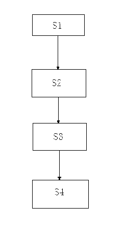
[0031] S1, input the roll diameter and the process speed of each roller in the first roller coating unit into the PLC control module, and the PLC control module calculates the theoretical roll surface linear velocity of each roll according to the process speed and the roll diameter of each roll (at first Calculate the theoretical rotational speed, theoretical rotational speed = process speed / Wu * roll diameter, and then calculate the theoretical roll surface linear speed according to the theoretical rotational speed, theoretical roll surface linear speed = theoretical rotational speed * roll diameter * Wu), so that the theoretical roll surface of each roll The line speed is consistent with the process speed, and the calculated theoretical roll surface line speed signals of each roll are respectively output to the servo control module with an encoder;

[0032] S2, the servo control module receives the theoretical roller surface speed signal of each roller from the PLC control ...

Embodiment 2

[0041] PLC control module, which stores the roller diameter and process speed data of each roller of the first roller coating unit, calculates the theoretical roller surface speed of each roller according to the process speed and the roller diameter of each roller, so that the theoretical roller surface speed of each roller Consistent with the process speed, and output the calculated theoretical roll surface speed signals of each roll respectively;

[0042] The servo control module has an encoder, the servo control module receives the theoretical roller surface speed signal from the PLC control module, and drives each roller according to the theoretical roller surface speed signal, and the encoder is used for Collect the actual roll surface speed of each roll, and output the actual roll surface speed signal of each roll to the PLC control module, so that the PLC control module adjusts the roll surface speed according to the actual roll surface speed signal and the theoretical r...

Embodiment 3

[0050] Further, in this embodiment, the first doctor blade 84 is in contact with the suction roller 82 at an angle less than 30 degrees; the second doctor blade 85 is in contact with the coating roller 83 at an angle greater than 30 degrees . Due to the different scraping positions of the suction roller 82 and the coating roller 83 at the same time, the first scraper 84 and the second scraper 85 are set to different angles, which can ensure that the suction roller 82 and the coating Scraping of roller 83.

[0051] In this embodiment, the roller coating equipment assembly 8 further includes a cleaning device 86, and the cleaning device 86 includes a liquid supply tank 861, a cleaning liquid delivery pump 862 for pumping the liquid supply tank 861, and the The cleaning liquid transmission pipe 863 communicated with the cleaning liquid transmission pump 862 and the spray pipe 864 communicated with the cleaning liquid transmission pipe. The spray pipe 864 is arranged above the ru...


PUM


Abstract

The invention provides a control method for a roller painting production line. According to the control method, the rotating speed of each roller and the process speed are enabled to be uniform by calculating and controlling the theoretic roller surface linear speed and the actual roller surface linear speed of each roller in a roller coating unit, and therefore the production efficiency is improved; and meanwhile, dislocation distances of patterns in multiple printing are calculated by using a secret identification technology so as to adjust the rotating speed of each roller, so that the patterns in multi-color printing are vivid and complete, and the printing length of the patterns is prolonged.

Description

technical field [0001] The invention relates to a control method and a control system for a roll coating and printing production line, belonging to the field of color steel plate production and manufacturing. Background technique [0002] Color-coated steel plate (commonly known as color-coated steel plate) refers to the metal base material that is firstly degreased by the continuous unit and subjected to surface passivation and other pre-coating treatments, and then passes through a color-coated printing machine to coat the surface with a Composite material formed after one or more layers of organic paint. [0003] In order to apply multi-color patterns, most coating production lines need to change the color of the paint several times a day. Two finishing coaters are installed in the position, among which No. 1 is the upper single-head coating machine, and No. 2 is the double-sided coating machine. However, in the color steel plate production line formed by this kind, th...

Claims


Application Information

Patent Timeline
Patent Type & Authority Applications(China)
IPC IPC(8): B41F33/16B41F33/00
CPCB41F33/00B41M1/10B41M1/14B41M1/28B41F33/16B05C1/0834B05C1/0873B41F9/01B41F9/023B41F13/0045B41F35/06B41P2235/26B41F3/00
Inventor 唐月平周建平
Owner LIAONING CHAOSHUO TOMA TECH STEEL PLATE PRINTING
Why Eureka
Try Eureka