
Integrated LED (Light Emitted Diode) chip and manufacturing method thereof

A technology for LED chips and manufacturing methods, which is applied in semiconductor/solid-state device manufacturing, electrical components, electrical solid-state devices, etc., can solve problems such as difficulty in making clear and tidy graphical interfaces, damage to equipment wafers, and excessive processes. Effective light-emitting area, reduced pitch, and simple production process

Active Publication Date: 2013-03-13
XIANGNENG HUALEI OPTOELECTRONICS
View PDF3 Cites 2 Cited by
  • Summary
  • Abstract
  • Description
  • Claims
  • Application Information

AI Technical Summary

Problems solved by technology

The current practice is still to use plasma etching method, but the thickness including the quantum well layer, N layer and buffer layer is generally 4-5μm, especially for the epitaxial layer of the PSS substrate, the thickness can reach more than 6μm. Etching such a deep depth requires high fidelity and high selectivity of masking materials and masking materials. In addition, it also places high demands on the etching process of ICP.
At present, the etching rate of the usual ICP is Calculated, it takes 75 minutes to etch a 6μm-deep isolation trench. The long-term plasma bombardment will inevitably cause damage to the equipment and the wafer itself, and it is difficult to make a clear and neat graphic interface.
[0005] A method for manufacturing light-emitting diodes that adopts step-by-step etching to form isolation grooves is proposed. Although this method solves the above-mentioned problems, there are still too many steps. Therefore, the present invention aims to provide a more convenient and effective process method

Method used


Image

  • Integrated LED (Light Emitted Diode) chip and manufacturing method thereof
  • Integrated LED (Light Emitted Diode) chip and manufacturing method thereof
  • Integrated LED (Light Emitted Diode) chip and manufacturing method thereof

Examples


Embodiment 1

[0044] A method for manufacturing an integrated LED chip, comprising the following steps:

[0045] 1. A sapphire substrate is used, and an epitaxial layer is grown on the substrate material. The epitaxial layer structure includes a buffer layer, an intrinsic semiconductor layer, a first semiconductor layer, a light-emitting layer and a second semiconductor layer from bottom to top.

[0046] 2. Routine cleaning of the epitaxial wafer; a protective layer is formed on the surface by means of evaporation, sputtering, vapor deposition, etc. The material of the protective layer is preferably silicon oxide material, and the thickness is preferably

[0047] 3. Use a laser cutting machine commonly used in the industry to laser cut the wafer according to the preset chip unit cell size. By adjusting the power of the laser to 0.9W and the moving speed of the laser cutting machine relative to the wafer monomer to 45mm / s, the The cutting depth is controlled at 6 μm; the section formed by ...


PUM


Abstract

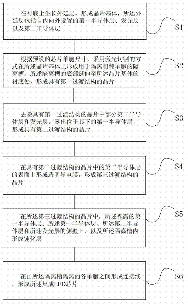
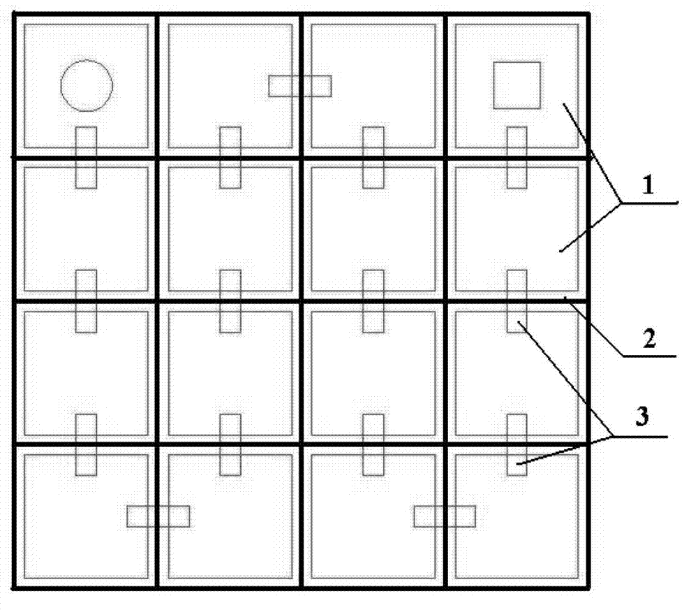
The invention discloses an Integrated LED (Light Emitted Diode) chip and a manufacturing method thereof. The method comprises the following steps of: S1, growing an epitaxial layer on a substrate to form a wafer matrix; S2, on the wafer matrix, forming an isolation groove for isolating adjacent mono-cells by laser cutting, wherein the bottom of the isolation groove stretches to the substrate of the wafer matrix; S3, removing a part of a second semiconductor layer and a emitting layer to enable a first semiconductor layer under the second semiconductor layer and the emitting layer to be exposed; S4, forming a transparent conductive film on the surface of the second semiconductor layer; S5, forming a passivation layer on a side wall and in the isolation groove, wherein the side wall formed by the superposition of the first semiconductor layer, the second semiconductor layer and the emitting layer; and S6, forming metal connecting wires among the mono-cells isolated by the isolation groove, so as to form the integrated LED chip. According to the Integrated LED (Light Emitted Diode) chip and the manufacturing method thereof disclosed by the invention, by forming the isolation groove by means of laser cutting, the manufacturing process is simplified, the production efficiency is improved, and the effective light-emitting area of the chip is increased.

Description

technical field [0001] The invention relates to the technical field of semiconductors, in particular to an integrated LED chip and a manufacturing method thereof. Background technique [0002] Arrayed high voltage / AC LED chips have become an important development direction for future LEDs, especially white LEDs, due to their obvious advantages in light efficiency and application fields. [0003] For a blue LED chip based on a sapphire substrate, an essential step in a general chip manufacturing method is to use plasma etching equipment to remove part of the P-type GaN and quantum wells to expose the N-type GaN. [0004] For integrated LED chips, the most important step is to form absolute electrical isolation between the unit cells of the integrated chip. That is, the connection of the N layer needs to be completely interrupted. The current practice is still to use the method of plasma etching, but the thickness including the quantum well layer, the N layer and the buffer ...

Claims


Application Information

Patent Timeline
Patent Type & Authority Applications(China)
IPC IPC(8): H01L33/00H01L21/762H01L27/15
Inventor 牛凤娟姚禹苗振林田艳红胡弃疾
Owner XIANGNENG HUALEI OPTOELECTRONICS
Learn More