
Meteor crater mismatching determination method based on ratio of shaded area to external-contour area

A shadow area and matching judgment technology, applied in the field of image processing, can solve problems such as mismatching, and achieve the effect of improving accuracy, accuracy and reliability

Inactive Publication Date: 2013-03-13
HARBIN INST OF TECH
View PDF1 Cites 7 Cited by
  • Summary
  • Abstract
  • Description
  • Claims
  • Application Information

AI Technical Summary

Problems solved by technology

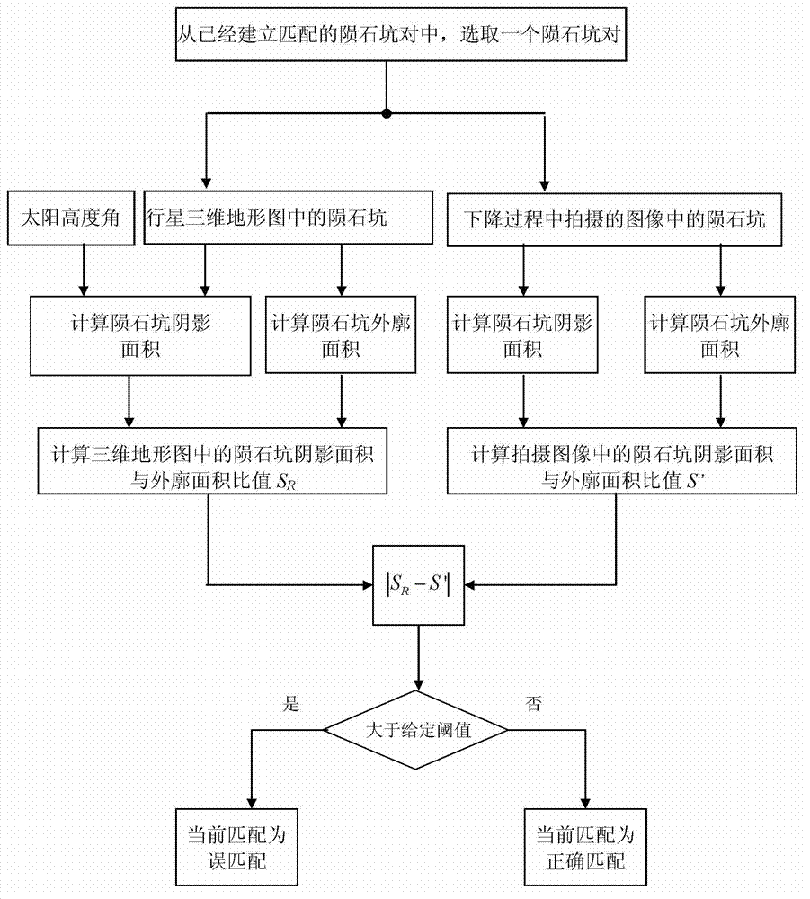
[0006] In order to solve the mis-match problem in the existing crater extraction and matching methods, the present invention proposes a crater mis-match judgment method based on the ratio of shadow area to outline area

Method used


Image

  • Meteor crater mismatching determination method based on ratio of shaded area to external-contour area
  • Meteor crater mismatching determination method based on ratio of shaded area to external-contour area
  • Meteor crater mismatching determination method based on ratio of shaded area to external-contour area

Examples


specific Embodiment approach 1

[0023] Specific implementation mode one: the crater mis-matching judging method based on the shadow area and the outline area ratio of the present embodiment, the specific steps are as follows:

[0024] Step 1: Select a pair of craters from the pairs of craters that have been matched, and the two craters of the pair of craters are respectively taken from the images taken during the descent of the planetary lander and the three-dimensional topographic map of the planet;

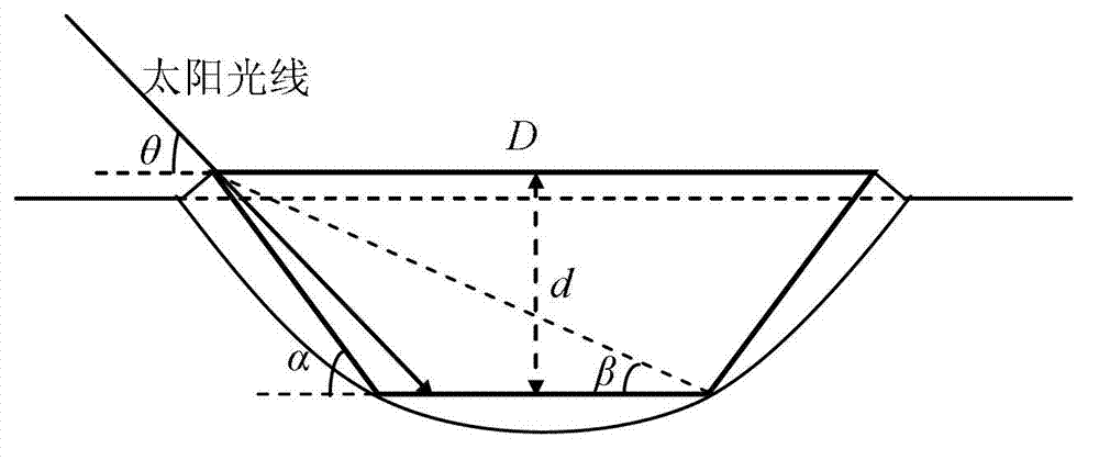
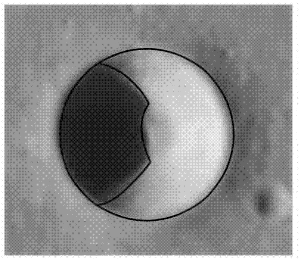
[0025] Step 2: Calculate the solar altitude angle θ when the image is taken during the descent of the planetary lander according to the ephemeris; select the crater from the 3D topographic map of the planet from the crater pairs in step 1, and then perform Trapezoidal simplified modeling to obtain a simplified 3D model; calculate the shadow area S in the crater based on the simplified 3D model and the solar altitude angle θ shadow The analytical solution of the crater is calculated according to the simplified ...

specific Embodiment approach 2

[0046] Specific embodiment 2: The difference between this embodiment and specific embodiment 1 is that the shadow area S in the crater is calculated according to the simplified three-dimensional model and the solar altitude angle θ described in step 2 shadow The analytical solution of is:

[0047] Through the long-term on-orbit observation of the probe, the size parameter information of the regular-shaped crater near the landing site is obtained, including the crater diameter D, the crater depth d, and the crater inclination α;

[0048] β = arccot ( D sin α - 2 d cos α + d cos α d sin α ) ...

specific Embodiment approach 3

[0060] Specific embodiment three: the difference between this embodiment and specific embodiment one or two is that if the solar altitude angle θ satisfies 0shadow for:

[0061] S shadow =2(S 1 +S 2 )

[0062] in:

[0063] S 1 = arcsin ( tan θ cot α ) · R 2 - R 2 · tan θ cot α · 1 - tan 2 θ cot 2 α 2

[0064] ...


PUM


Abstract

The invention provides a meteor crater mismatching determination method based on ratio of shaded area to external-contour area, and relates to the technical field of image processing, solving the problem of mismatching of conventional meteor crater extracting and matching method. The meteor crater mismatching determination comprises the following steps in sequence: selecting a meteor crater pair from the meteor crater pairs which are given the matching; calculating the altitude angle Theta of the sun at the image shooting time based on the ephemeris; calculating the ratio SR of the shaded area to the external-contour area, from the three-dimensional topography, of the meteor crater according to the three-dimensional model of the meteor crater and the altitude angle Theta of the sun; calculating the ratio S' of the shaded area to the external-contour area, from the image shot during falling, of the meteor crater; and if the absolute value of SR-S' is more than a given threshold, determining that the selected meteor crater is subjected to mismatching. According to the meteor crater mismatching determination method based on the ratio of the shaded area to the external-contour area, the mismatched meteor crater is removed from the meteor crater pairs which are given the matching after the matching between the meteor crater in the image which is shot when a lander falls and the meteor crater in the planetary three-dimensional topography is accomplished, and thus the accuracy in matching of the meteor crater can be improved.

Description

technical field [0001] The invention relates to the technical field of image processing, in particular to a crater mismatch judgment method based on the ratio of shadow area to outline area. Background technique [0002] The crater is the most prominent topographical feature on the surface of the planet. It has a relatively consistent geometric shape and clear outline, which is easy to match and track. In the planetary landing mission, the crater can be used as a navigation guidepost for the planetary landing section to improve the accuracy of the navigation system. precision. In the task of navigation based on crater landmarks, the extracted craters are required to have a high degree of confidence, and can be successfully matched with the craters in the three-dimensional topographic map of the planet during most of the landing process. [0003] Compared with the two-dimensional image map of the planet, the three-dimensional topographic map of the planet contains dimensiona...

Claims


Application Information

Patent Timeline
IPC IPC(8): G06T7/00
Inventor 徐田来崔祜涛田阳余萌
Owner HARBIN INST OF TECH
Learn More