Composite flow baffling water treatment biomembrane reactor

A biofilm reactor and flow water treatment technology, applied in the field of water treatment, can solve the problems of many sludge outlets, large power consumption, and less biofilm, and achieve less sludge production, good hydraulic conditions, and convenient emptying Effect

Active Publication Date: 2013-03-06
HANGZHOU ACAD OF AGRI SCI
View PDF4 Cites 13 Cited by
  • Summary
  • Abstract
  • Description
  • Claims
  • Application Information

AI Technical Summary

Problems solved by technology

This kind of reactor cannot handle water with high dissolved oxygen. If it is aerated, the dissolved oxygen in the whole reactor will be too high, which is not conducive to nitrogen removal. If it is not aerated, it will not be able to operate. The aeration can only adjust the reactor. Dissolved oxygen, and the amount of biofilm is small, power consumption is large, and there are many sludge discharge outlets. Therefore, it is necessary to develop a new type of bioreactor for complex and changeable wastewater treatment.

Method used


Image

  • Composite flow baffling water treatment biomembrane reactor
  • Composite flow baffling water treatment biomembrane reactor

Examples


Embodiment 1

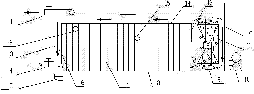
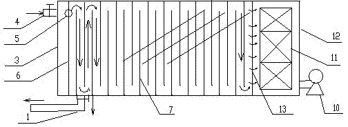
[0027] Such as figure 1 , 2 A compound baffle water treatment biofilm reactor shown in the figure is divided into an anoxic zone and an aerobic zone by an inflow partition 6, an outflow partition 13 and an advection plate 14 in a rectangular tank body. and the leveling zone, the top of the leveling plate 14 is the advection zone, the bottom is the anoxic zone, and the area on the right side of the outflow partition 13 is the aerobic zone.

[0028] The anoxic zone is surrounded by the horizontally arranged flow plate 14 and the vertically arranged inflow partitions 6 and outflow partitions 13 on both sides, forming a relatively independent semi-closed anoxic environment. Between the inlet partition 6 and the outlet partition 13, there are baffles 7 arranged in parallel, and the gap between adjacent baffles is 15 centimeters. The plate 14 is connected, and there is a gap between the dividing plate and the pool bottom plate 8, and the gap is 10 cm; the upper part of the baffle ...

Embodiment 2

[0050] Utilize this composite baffle water treatment biofilm reactor to treat nutrient-rich surface water, the gap between the adjacent baffles of the reactor is 30 cm, and the gap between the partition plate and the bottom plate 8 of the pool is 20 cm; the width of the baffle plate and the opposite surface The pool wall gap is 30 centimeters, the gap between the inlet partition 6 and the adjacent left pool wall 3 is 20 centimeters, the number of baffles is 28, and the aerobic zone is equipped with 9 groups of square vertical porous carriers 11, and the water depth in the advection zone is It is controlled at 1 / 5 of the water depth of the entire reactor; the area of ​​the aerobic zone accounts for 1 / 3 of the pool body. Intermittent aeration and circulating water pump 10 are used for internal circulation. The concentration of ammonia nitrogen in the water is 3-10mg / L, and the concentration of total nitrogen is 5-20mg / L. Continuous operation is adopted, and the natural film-hangi...

Embodiment 3

[0052] Utilize this composite baffle water treatment biofilm reactor to process the aquaculture water in the soft-shelled turtle outer pond, the gap between the adjacent baffles of the reactor is 10 centimeters, and the gap between the dividing plate and the bottom plate 8 of the pond is 10 centimeters; The pool wall gap on the surface is 15 centimeters, the gap between the inlet partition 6 and the adjacent left pool wall 3 is 9 centimeters, the number of baffles is 15, and the aerobic zone carrier is equipped with 5 groups of square vertical porous carriers 11, advection The water depth of the zone is controlled at 1 / 4 of the water depth of the entire reactor; the area of ​​the aerobic zone accounts for 1 / 4 of the pool body. Without aeration 9, only circulating water pump 10 is used for internal circulation. The concentration of ammonia nitrogen in the water is 1-10mg / L, and the concentration of total nitrogen is 2-32mg / L. Continuous operation is adopted, and the natural film...


PUM


Abstract

The present invention discloses a composite flow baffling water treatment biomembrane reactor, which comprises a water inlet, a water outlet and a vent nozzle, and is characterized in that a reactor is divided into relatively independent three zones such as an anoxia zone, an aerobic zone and a flat flow zone in a rectangular pool through a flow inlet separator, a flow outlet separator and a flat flow plate; the anoxia zone comprises the horizontally-arranged flat flow plate, the flow inlet separator and the flow outlet separator, wherein the flow inlet separator and the flow outlet separator are connected with the lower sides of both ends of the flat flow plate, and a plurality of flow baffling plates are arranged between the flow inlet separator and the flow outlet separator; a width of the flat flow plate is the same as a width of the pool; a width of the separator is the same as a width of the pool, and a certain distance is arranged between the separator and the left pool wall, the separator and the right pool wall, and the separator and a pool bottom plate; the flow baffling plate has a porous structure, the upper end is connected with the flat flow plate, the lower end is connected with the pool bottom plate, one side is connected with the front pool wall or the rear pool wall, a gap is arranged between the other side and the rear pool wall or the front pool wall, and the adjacent flow baffling plates are arranged in a dislocation manner; the aerobic zone is arranged between the flow outlet separator and the pool wall, the middle is provided with a porous carrier, and an aeration head is arranged on the lower portion of the aerobic zone; and one side of the aerobic zone is provided with a circulating water pump. According to the present invention, the aerobic zone and the anoxia zone are separately and independently controlled, such that mutual interference can be reduced, a good treatment can be provided, a process is easy to operate, and the reactor can be applicable for bioremediations of eutrophication water bodies, aquaculture water bodies and even industrial wastewater.

Description

technical field [0001] The invention relates to water treatment technology, in particular to a bioreactor for denitrification and dephosphorization of waste water by using biofilm technology. Background technique [0002] With the rapid development of industry and agriculture and the continuous improvement of people's living standards, the degree of eutrophication in urban water bodies caused by domestic sewage, farmland drainage and irrigation water, industrial wastewater, aquaculture, and large-scale livestock and poultry manure discharged into rivers is serious. Water resources are suffering from different degrees of pollution, the ecological environment of water bodies is deteriorating day by day, and biodiversity has been severely damaged, which not only affects the normal life of human beings, but also restricts economic development. Among them, the treatment of high nitrogen wastewater has always been a difficult problem. [0003] Because bioremediation has the advan...

Claims


Application Information

Patent Timeline
Patent Type & Authority Applications(China)
IPC IPC(8): C02F3/30
Inventor 牛天新
Owner HANGZHOU ACAD OF AGRI SCI
Why Eureka
Try Eureka