A Design Method for Composite Airfoil Fan Blades

A technology of airfoil blade and design method, which is applied in the direction of mechanical equipment, machine/engine, liquid fuel engine, etc., can solve the problems of high mold investment cost, low operating efficiency, high noise, etc. Effect

Active Publication Date: 2016-03-16
王书勤
View PDF9 Cites 1 Cited by
  • Summary
  • Abstract
  • Description
  • Claims
  • Application Information

AI Technical Summary

Problems solved by technology

These literatures solve the computational flow pattern of some axial flow fans, but there are still some deficiencies, because there are many computational flow patterns of turbine impeller blades, and the structure is generally classified into three categories: axial flow, centrifugal, mixed flow, The blades in the previous literature obviously cannot meet the engineering design requirements in application.
In order to reduce the noise in the design of the axial flow fan, the blade forward-swept structure is adopted in many occasions, because the airfoil rectangular blade and the airfoil blade with trailing edge mentioned in the previous literature cannot be used to realize the calculated flow pattern and structure, usually It is realized by precision casting, injection molding, die-casting and other methods, which makes the manufacturing cost of the fan high, the investment cost of the mold is large, and the versatility between different machine numbers is poor; and the conventional centrifugal and mixed-flow impellers mostly use single-plate blades, although The manufacturing process is simplified, but at the same time, it also results in low operating efficiency, narrow range of working conditions and high noise
Although some impellers use airfoil blades, most of them are limited to manual patchwork welding, the accuracy of the airfoil is poor, the production cost is high, and it is not suitable for mass production

Method used


Image

  • A Design Method for Composite Airfoil Fan Blades
  • A Design Method for Composite Airfoil Fan Blades
  • A Design Method for Composite Airfoil Fan Blades

Examples


Embodiment 1

[0031] Example 1: Generation of Composite Airfoil

[0032] Composite airfoil generation mode of the present invention is divided into following six categories:

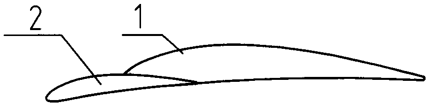
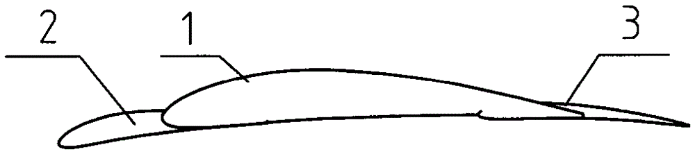
[0033] ① Leading edge superimposed compound airfoil: the standard airfoil is used as the main body of the airfoil blade, and the leading edge of the main body of the airfoil blade is extended to superimpose the airfoil so that the superimposed airfoil coincides with the pressure surface line of the main body of the airfoil blade, that is wing

[0034] The radius of curvature of the pressure surface of the main body of the airfoil and the radius of curvature of the pressure surface of the superimposed airfoil are tangent at the joint point, the maximum thickness of the superimposed airfoil is smaller than the maximum thickness of the main body of the airfoil, and the main body of the airfoil is Smooth transition between profile and superimposed airfoil profiles.

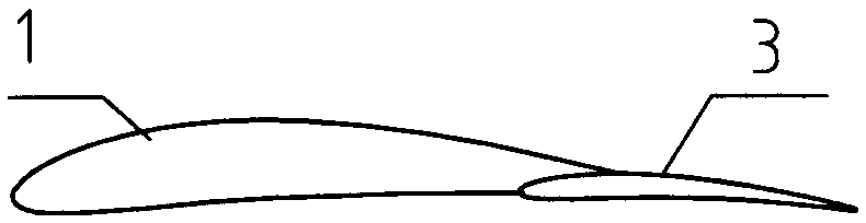
[0035] ②Composite airfoil superimposed on the trailin...

Embodiment 2

[0039] ⑥ Composite airfoil superimposed on the suction surface: the standard airfoil is used as the main body of the airfoil blade, and the airfoil is superimposed on the suction surface of the subject airfoil. On the suction surface, the main shape line of the airfoil blade and the superimposed airfoil shape line are smoothly transitioned. Embodiment 2: select the type of composite airfoil, and determine the section form

[0040] (1) Determine the airfoil profile line using the composite airfoil according to the engineering calculation flow pattern.

[0041] (2) The section size of the composite airfoil is not large, or the solid structure of the composite airfoil can be selected when considering the conditions of blade wear resistance, strength, and stiffness, etc.

[0042] (3) When the section size of the composite airfoil is large, different forms of hollow section structures can be selected under the conditions of blade strength and stiffness.

[0043] (4) When the sect...

Embodiment 3

[0044] Example 3: blade profile material

[0045] According to the different media (occasions) applicable to the impeller blades, different materials are selected. The blade material can be metallic material, non-metallic material, composite material.


PUM


Abstract

The invention provides a design method of a composite airfoil fan blade. The method comprises the steps that a standard aerial aerodynamic force airfoil is adopted as an airfoil blade main body of a composite airfoil; the front edge of the airfoil blade main body extends forward for airfoil superposition; or the back edge of the airfoil blade main body extends backward for the airfoil superposition; or the front edge of the airfoil blade main body extends forward and the back edge of the airfoil blade main body extends backward for the airfoil superposition simultaneously; the airfoil superposition is conducted on the suction surface of the airfoil blade main body; and the novel airfoil is composited. The composite airfoil can meet aerodynamic force requirements of different impellers by cutting and trimming a front edge extension airfoil and a back edge extension airfoil, changing a blade angle, changing a relative torsion angle, adjusting blade numbers, changing chord length according to a used calculation flow pattern and a use occasion. The method realizes mass production of blades, is high in generality, is particularly applied to the various fan and minitype wind power industries, and has a very good popularization value.

Description

technical field [0001] The present invention relates to the technical field of wind turbines and wind power, in particular to a design method for composite airfoil fan blades, that is, using the aerodynamic standard airfoil as the main body of the airfoil blade, extending on the leading edge and the trailing edge of the main body of the airfoil blade. A method of adding an airfoil to generate a composite airfoil, or adding an airfoil to the suction surface of an airfoil blade body to generate a composite airfoil. Background technique [0002] The performance of turbomachinery largely depends on the structure and shape of the turbine impeller blades. Existing airfoil blade technologies often use molding, die forging, precision milling, and manual shaping methods for processing, which is difficult to process. , the production cost is high, and it is difficult to form large-scale production. In order to solve the production of turbine impeller blades, relevant literature intro...

Claims


Application Information

Patent Timeline
Patent Type & Authority Patents(China)
IPC IPC(8): F04D29/26
Inventor 王书勤
Owner 王书勤
Why Eureka
Try Eureka