Apparatus and method for removal of surface oxides via fluxless technique involving electron attachment
An electron and electron emission technology used in chemical instruments and methods, auxiliary devices, cleaning methods and utensils, etc.
- Summary
- Abstract
- Description
- Claims
- Application Information
AI Technical Summary
Problems solved by technology
Method used
Image

Examples
Embodiment 1
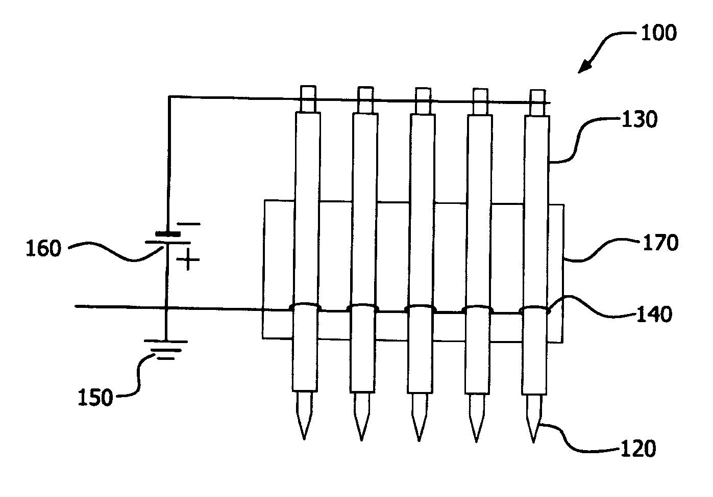
[0078] The field emission device used in this embodiment, such as figure 2 As shown, it contains 5 stainless steel cathode needles, each of which is tightly inserted into the dielectric material, which constitutes an alumina ceramic tube (inner diameter (I.D.) 0.46 mm, outer diameter (O.D) 1.2 mm), which is mounted on a ceramic board. The spacing between the cathode pins is 5 mm. The tip of each cathode needle protruded about 1.0 mm outside the corresponding alumina ceramic tube. An anode wire is wrapped around each of the 5 tubes and electrically grounded. The surrounding anode wire is spaced 10 mm from the end of the tube towards the tip side of the cathode needle. Place the thus prepared structure at room temperature in a 2 N 2 Purged quartz tube furnace. When the pulsed (10KV) negative voltage potential applied to the 5 cathode needles was increased to -3.7KV, all 5 needle tips started emitting electrons. When electron emission starts on the needle, due to the gas ...
Embodiment 2
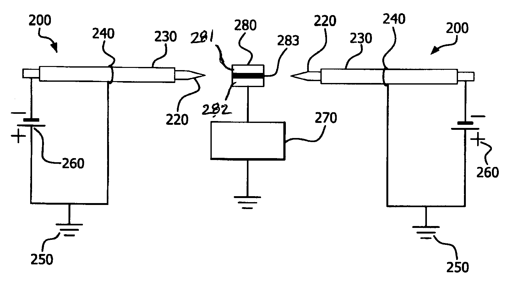
[0080] test as image 3 Field emission device structure constructed as shown, containing two stainless steel cathode pins, each inserted into a ceramic (alumina) tube or dielectric material, mounted on a die resting on a copper plate Secure both sides of the sample. Die-mounted samples are conductive and grounded. The distance between the tip of each needle and the edge of the sample is 5.5 mm. The tip of each cathode needle extended 1.0 mm outside the corresponding dielectric tube. An anode wire is wrapped around each of the two dielectric materials or tubes and is electrically grounded. The surrounding anode wire is spaced 10 mm from the end of the tube towards the needle tip side. Place the thus prepared structure at room temperature in a bath containing 4 vol% H 2 N 2 Purged quartz tube furnace. When the pulsed (10KV) negative voltage potential applied to the 2 needles increases to -1.9KV, the 2 needle tips light up blue, indicating electron emission. When the samp...
Embodiment 3
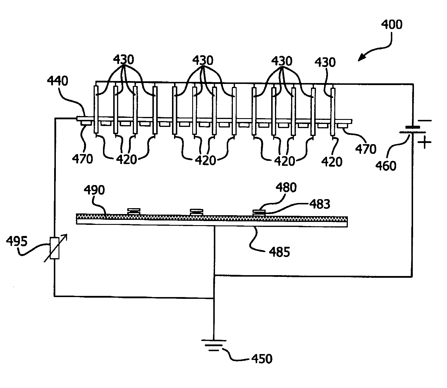
[0082] and figure 2 and image 3 The same field emission device structure and sample arrangement described in 2 N 2 Tested in a purged quartz tube furnace. The die-attach sample consisted of a flux-free gold / tin solder pellet (melting point 280°C) sandwiched between gold / nickel-coated ceramic and gold / nickel-coated copper to simulate a die-attach device. The 3 die-mounted samples each had the same dimensions: 3 mm × 6 mm. To demonstrate electron attachment (EA) activation at N 2 H in 2 For fluxless die attach feasibility, a pulsed (10KV) negative voltage potential was applied to the 2 pins at room temperature. When the applied voltage was increased to -1.8KV, the 2 needle tips lit up blue, indicating electron emission. The current received on the sample was -0.45 mA. The samples were then heated to 290°C with a ramp time of 2 minutes, soaked at 290°C for 1 minute, and then cooled. Electron attachment (EA) is maintained during temperature ramping and holding. It was ...
PUM
 Abstract
Description
Claims
Application Information
 - R&D
- Intellectual Property
- Life Sciences
- Materials
- Tech Scout
- Unparalleled Data Quality
- Higher Quality Content
- 60% Fewer Hallucinations
Browse by: Latest US Patents, China's latest patents, Technical Efficacy Thesaurus, Application Domain, Technology Topic, Popular Technical Reports.
© 2025 PatSnap. All rights reserved.Legal|Privacy policy|Modern Slavery Act Transparency Statement|Sitemap|About US| Contact US: help@patsnap.com