Numerical control equipment

A numerical control equipment and guide technology, applied in metal processing equipment, large fixed members, feeding devices, etc., can solve the problems of fast wear of moving parts, affecting processing accuracy, inaccurate positioning, etc., and achieve good guiding effect

Inactive Publication Date: 2013-02-06
杨东佐
View PDF2 Cites 5 Cited by
  • Summary
  • Abstract
  • Description
  • Claims
  • Application Information

AI Technical Summary

Problems solved by technology

[0004] In the above-mentioned prior art, the ram on which the main shaft is installed is placed on one side of the screw rod, and is movably connected with the screw rod. The connection between the ram and the screw rod is used for bearing, and the center of gravity deviates from the axis of the screw rod. When the main shaft moves up and down, the unbalanced motion produces torsion, which makes the main shaft deviate from the direction of the screw shaft axis, resulting in poor stability and inaccurate positioning of the main shaft during movement. , Unsmooth motion, large motion inertia, and fast wear of moving parts further affect the processing accuracy

Method used


Image

  • Numerical control equipment
  • Numerical control equipment
  • Numerical control equipment

Examples


Embodiment 1

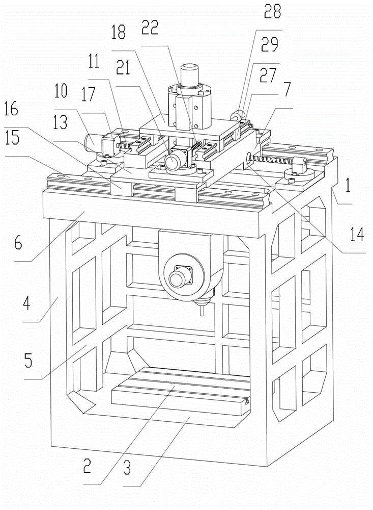
[0022] Such as Figure 1 to Figure 4 As shown, a numerical control device includes a main body frame 1 and a workbench 2 integrally formed. The main body frame 1 includes a square base 3, which is integrally formed with the base 3 and is arranged at the four corners of the base 3 and the main support columns 4 respectively arranged at the middle positions of the left side, the right side and the rear side of the base, connecting the main support columns 4 Between horizontal connecting column 5. The main support frame 6 arranged on the main support column 4 is integrally formed with the main support column 4 . The main support frame 6 is a square closed-loop structure with an opening facing the vertical direction.

[0023] It also includes the X-direction sliding seat 7. Between the main support frame 6 and the X-direction sliding seat 7, there are mutually matched X forward guide rails and X backward guide rails. The X slide seat 7 can slide back and forth along the X forw...

Embodiment 2

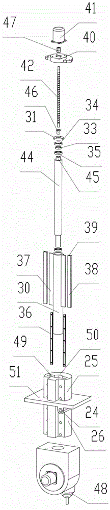
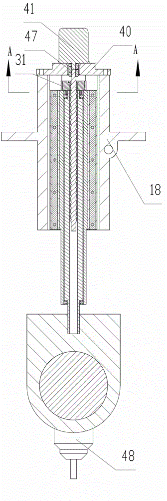
[0038] Such as Figure 5 As shown, a numerical control device is different from Embodiment 1 in that a main shaft 61 is installed in the Z guide rod 60, the tool holder 62 of the main processing head is directly fixed on the main shaft 60, and the tool 63 is fixed on the tool holder. Head 62 on.

[0039] In the present invention, the main processing head may be provided with a tool clamping head, or the main processing head may be a paint spraying head, a welding gun, a laser gun, a plasma cutting gun, a screw gun or a gas cutting gun. When a milling cutter is installed on the tool chuck, the function of milling can be realized; when a grinding wheel is installed on the tool chuck, the function of grinding can be realized; when a boring tool is installed on the tool chuck , the function of boring can be realized; when the drill bit is installed on the tool holder, the function of drilling can be realized; when the main processing head is a painting head, the function of spray...


PUM


Abstract

Numerical control equipment comprises a Z-direction guiding device, a sliding seat mounted with the Z-direction guiding device, a sliding seat fixing device, a sliding seat driving device, a workpiece clamping device and a main processing head, further comprises a Z-direction linear guiding rail accommodating hole which penetrates a Y-direction sliding seat and a convex part of the sliding seat, wherein the sliding seat comprises a sliding seat baseplate and a convex part; the convex part protrudes out of the sliding seat baseplate; a first fixing plane is arranged on the outer side surface of the convex part; the Z-direction guiding device comprises a Z-direction guiding rod and a Z-direction guiding rail driving device; one side surface of the Z-direction linear guiding rail accommodating hole is a second fixing plane parallel to the first fixing plane; two first Z-direction linear guiding rail orbits are fixed on the second fixing plane; second Z-direction linear guiding rail orbits are arranged on the Z-direction guiding rod; and the main processing head is arranged under the Z-direction guiding rod. The numerical control equipment has the advantages that the guiding effect is good; a rotating prevention structure is required to be designed additionally; and when the first Z-direction linear guiding rail orbits and the second Z-direction linear guiding rail orbits are abraded, all that is needed is to replace the first Z-direction linear guiding rail orbits and the second Z-direction linear guiding rail orbits.

Description

technical field [0001] The present invention relates to a numerical control equipment, in particular to a main processing head numerical control machine tool, numerical control painting equipment, numerical control welding equipment, numerical control laser cutting equipment, numerical control laser welding equipment, numerical control plasma cutting equipment, numerical control screw mounting equipment, numerical control gas cutting equipment Wait. Background technique [0002] Existing CNC equipment with a gantry structure, such as the invention patent application number 201010284237.9, discloses a CNC gantry vertical compound machine tool, including a base, a workbench, and a column. The columns are movably connected by column guide rails or by fasteners. The composite beam is fixedly connected, and the composite beam is flexibly connected through the beam guide rail or fixedly connected with more than two sliding saddles through the fasteners, and the sliding saddle is f...

Claims


Application Information

Patent Timeline
IPC IPC(8): B23Q37/00B23Q1/26B23Q5/40
Inventor 杨东佐
Owner 杨东佐
Why Eureka
Try Eureka