
Steel bar concrete beam reinforcing structure with partially restrained steel truss

A technology for reinforced concrete beams and reinforced structures, which is applied in building construction, building maintenance, construction, etc., can solve the problems of insignificant improvement in shear resistance, complex construction technology, and small bearing potential, and achieves improved bending and shearing capacity. The effect of safety, ensuring the quality of reinforcement, and reducing the difficulty of construction

Inactive Publication Date: 2013-01-30
NANJING UNIV OF TECH
View PDF2 Cites 37 Cited by
  • Summary
  • Abstract
  • Description
  • Claims
  • Application Information

AI Technical Summary

Problems solved by technology

[0003] The existing various beam strengthening technologies generally require a large number of grinding and drilling constructions on the beam body to be strengthened. Reinforcement for the bending performance of the beam does not improve its shear performance significantly, thus reducing the reinforcement effect; in addition, construction steps such as on-site welding and glue application are often required during construction, and the reinforcement effect is significantly affected by the cementing materials and the quality of on-site construction. Constraints; Finally, for old buildings or lightweight concrete components, the concrete strength is generally low. Due to the small load-bearing potential of the beam body to be strengthened, it is difficult to meet the reinforcement design requirements with existing reinforcement technologies, and the concrete components with serious surface weathering, Various existing technologies will have technical difficulties, such as post-glue fiber composite materials or the bonding of steel plates and beams is difficult to guarantee, etc.

Method used


Image

  • Steel bar concrete beam reinforcing structure with partially restrained steel truss
  • Steel bar concrete beam reinforcing structure with partially restrained steel truss

Examples


Embodiment Construction

[0015] The present invention will be further described below in conjunction with the accompanying drawings and specific embodiments.

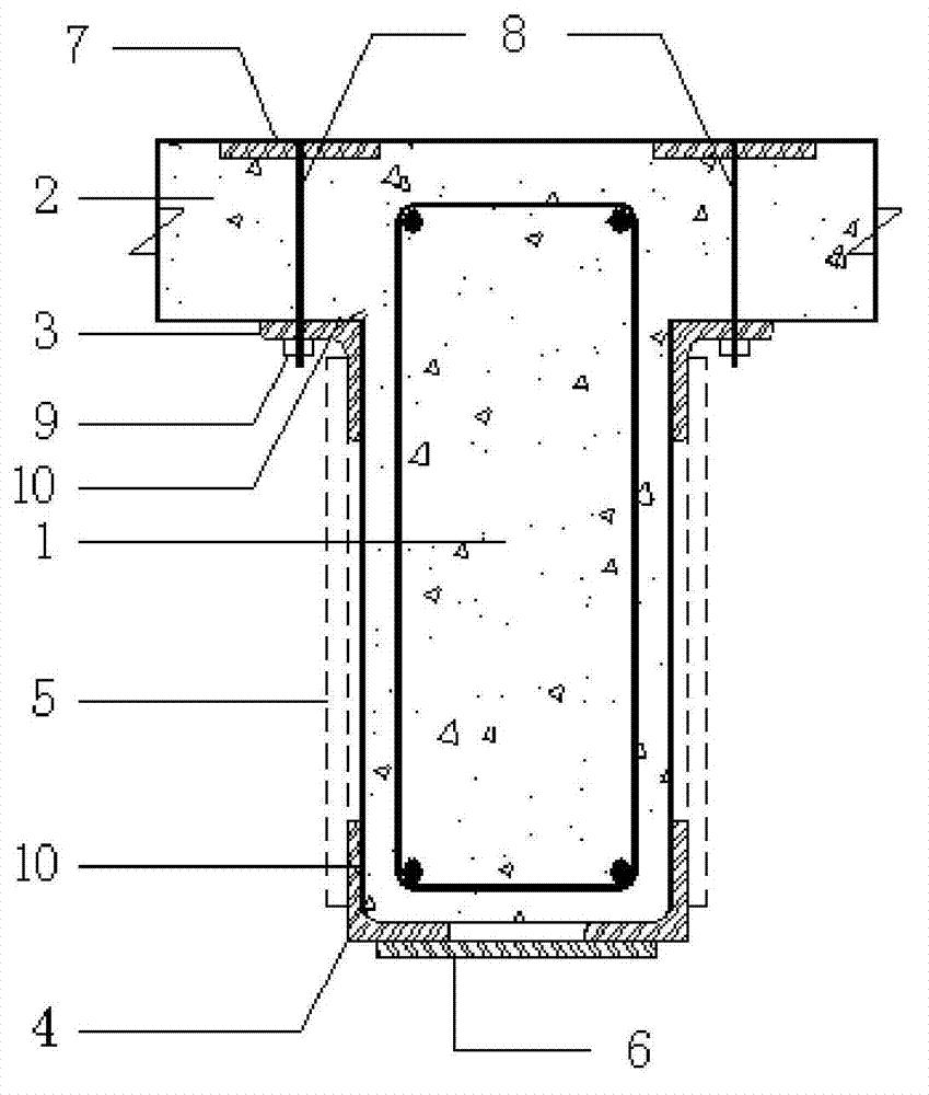
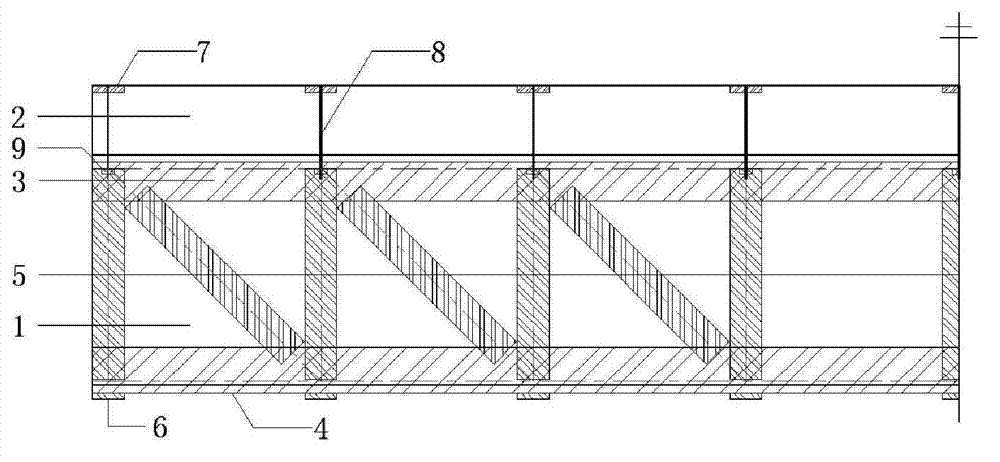
[0016] Such as figure 1 and 2 Shown: a steel truss partially restrained reinforced concrete beam reinforcement structure, including upper angle steel 3, lower angle steel 4, web panel 5, bottom plate steel plate 6, anchor steel plate 7, shear anchor bolt 8 and bolt 9, the upper The angle steel 3, the lower angle steel 4, the web panel 5 and the base steel plate 6 groups are combined to form an open steel truss tightly enclosing the beam 1 to be reinforced. The lower angle steel 4 is respectively installed on the two lower corners of the beam 1 to be strengthened. 4 are connected by a bottom plate steel plate 6, the upper angle steel 3 is installed between the beam 1 to be reinforced and the floor 2, the upper angle steel 3 and the lower angle steel 4 are connected by a web panel 5, and the anchor steel plate 7 is set on In the concrete protec...


PUM


Abstract

The invention discloses a steel bar concrete beam reinforcing structure with a partially restrained steel truss, comprising upper angle steel, lower angle steels, a web batten plate, a bottom steel plate, an anchored steel plate, a shear resistant anchor bolt and a bolt, wherein the upper angle steel, the lower angle steels, the web batten plate and the bottom steel plate are spliced to form an opened steel truss for tightly hooping a beam to be reinforced, the lower angle steels are respectively arranged at two lower corners of the beam to be reinforced and are connected with each other by the bottom steel plate, the upper angle steel is mounted between the beam to be reinforced and a slab, and is connected with the lower angle steels by the web batten plate, the anchored steel plate is arranged in the slab and is connected with the shear resistant anchor bolt arranged in the slab, and the shear resistant anchor bolt is connected with the upper angle steel by the bolt in a pre-fastening mode. The steel truss and the steel bar concrete beam form two load bearing protection lines, so the bearing capacity of the steel bar concrete beam meets the reinforcing design requirement, and the safety of a member and a structure can be ensured.

Description

technical field [0001] The invention relates to a steel truss partially constrained beam reinforcement structure, which belongs to the technical field of concrete structure reinforcement in construction engineering. Background technique [0002] Reinforced concrete beams are flexural components, and their reinforcement is mainly to increase their flexural bearing capacity, so as to achieve the purpose of reinforcement and reinforcement. At present, there are a variety of mature and widely used beam-type bending member reinforcement technologies, mainly including enlarging section reinforcement method, external prestress reinforcement method, pasting fiber composite reinforcement method, pasting steel plate reinforcement method and adding fulcrum reinforcement method, etc. Wait. [0003] The existing various beam strengthening technologies generally require a large number of grinding and drilling constructions on the beam body to be strengthened. Reinforcement for the bendi...

Claims


Application Information

Patent Timeline
IPC IPC(8): E04G23/02
Inventor 朱张峰
Owner NANJING UNIV OF TECH
Learn More