
Ultra-wide spectrum rear-feed shock pulse reflection surface antenna system

An antenna system and shock pulse technology, applied in the field of microwave electronics, can solve the problems of large antenna feeder loss, unfavorable azimuth rotation and pitch, etc., and achieve the effect of increasing the length of the pole plate, improving the low frequency and high frequency characteristics, and large radiation gain

Active Publication Date: 2013-01-23
INST OF APPLIED ELECTRONICS CHINA ACAD OF ENG PHYSICS
View PDF1 Cites 10 Cited by
  • Summary
  • Abstract
  • Description
  • Claims
  • Application Information

AI Technical Summary

Problems solved by technology

[0007] In order to overcome the above-mentioned problem that the ultra-broadband feed-forward shock pulse reflector radiation antenna has a large feeder loss and is not conducive to the realization of azimuth rotation and pitching, the present invention provides an ultra-broadband feed-back shock pulse reflector antenna system, which can realize The pulse signal is fed into the bottom of the pot, the length of the feeder is short, and the structure of the whole system is compact

Method used


Image

  • Ultra-wide spectrum rear-feed shock pulse reflection surface antenna system
  • Ultra-wide spectrum rear-feed shock pulse reflection surface antenna system
  • Ultra-wide spectrum rear-feed shock pulse reflection surface antenna system

Examples


Embodiment Construction

[0025] The present invention will be further described below in conjunction with the accompanying drawings.

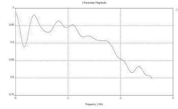
[0026] figure 1 It is a structural schematic diagram of the ultra-wide spectrum rear-feed shock pulse reflector antenna system of the present invention, figure 2 is a structural schematic diagram of the balun in the present invention, image 3 It is a structural schematic diagram of the exponential TEM horn in the present invention.

[0027] exist figure 1 Among them, the ultra-broadband back-fed shock pulse reflector antenna system of the present invention includes: a parabola 1 , a balun 2 , an index TEM horn 3 , and a secondary reflector 4 . The connection method is that the coaxial part of the balun is connected with the coaxial feeder of the pulse power source; the flat part is connected with the feed-in end of the index TEM horn; the sub-reflector is installed at a certain distance from the index TEM horn The index TEM horn is installed at a position with a ...


PUM


Abstract

The invention discloses an ultra-wide spectrum rear-feed shock pulse reflection surface antenna system. The ultra-wide spectrum rear-feed shock pulse reflection surface antenna system consists of a balance converter, an index transverse electromagnetic (TEM) horn, a secondary reflection plate and a paraboloid; one end of the balance converter of the system is connected with coaxial feeders of a pulse source; the other end of the balance converter is connected with a TEM horn combined feed source; the balance converter finishes the feeding from asymmetric coaxial feeders to a symmetry index TEM horn to keep the balance of an antenna feed system; and simultaneously, the balance converter also has an effect of impedance conversion. By gradually changing the height and the width of a polar plate of the index TEM horn, the length of the polar plate is increased correspondingly; low-frequency characteristics and high-frequency characteristics of the horn are improved; the generation of a traverse electric (TE) mode and the production of a transverse magnetic (TM) mode are inhibited; forward radiation of the horn is converted into backward radiation by the secondary reflection plate and the index TEM horn; and the maximum radiation gain of an antenna can be obtained by optimally designing structural parameters of each part of the ultra-wide spectrum rear-feed shock pulse reflection surface antenna system.

Description

technical field [0001] The invention belongs to the field of microwave electronics, and in particular relates to an ultra-wide-spectrum back-fed shock pulse reflector antenna system. Background technique [0002] In the ultra-broadband shock pulse reflector antenna design, since the source signal has more low-frequency components and the main lobe of the feed horn pattern is wider, the feedforward reflector antenna method is generally used. In the design of the feedforward reflector antenna, the feeder line is usually long and the loss of the feeder line is large, and it is not conducive to the realization of the azimuth rotation and pitch of the antenna in engineering. [0003] There are two commonly used methods for the design of the balun between the feed TEM horn and the high-power pulse coaxial transmission line. One is the point contact type, which directly connects the inner core of the coaxial structure to the pole plate of the TEM horn antenna. Coaxial connection, ...

Claims


Application Information

Patent Timeline
Patent Type & Authority Applications(China)
IPC IPC(8): H01Q13/02H01Q19/19
Inventor 廖勇谢平陈志刚徐刚陆巍扬周炳孟凡宝
Owner INST OF APPLIED ELECTRONICS CHINA ACAD OF ENG PHYSICS
Learn More