Rifled tube extruding method
A technology of internally threaded pipe and extrusion method, which is applied in the direction of metal extrusion, metal extrusion forming tools, metal processing equipment, etc., can solve the problem of high welding requirements for internally threaded aluminum pipes and raw material copper strips that cannot be produced in a large scale. , poor mechanical properties of products and other problems, to achieve the effect of easy organization of large-scale production, low production cost and high degree of automation
- Summary
- Abstract
- Description
- Claims
- Application Information
AI Technical Summary
Problems solved by technology
Method used
Image
Examples
Embodiment 1
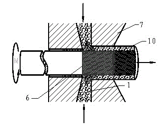
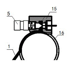
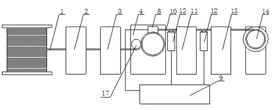
[0022] Embodiment 1: Extrusion steps of the internally threaded aluminum rod of this embodiment: as figure 2 and 3 As shown, after the aluminum rod 1 is cleaned and straightened by the straightening device 2 and the cleaning device 3, it is sent into the die cavity 15 of the tangential continuous extrusion machine, and the feed formed by the extrusion wheel groove 16 and the pressing wheel 17 The material inlet enters the mold cavity, and the temperature of the mold cavity is 480°C (the speed control loop is composed of the speed control system 6, the motor 5, and the signal acquisition device 12) (such as figure 1 (indicated by the middle arrow), fill the tooth grooves of the threaded mandrel 6, and weld it into an internally threaded aluminum tube 10 that meshes with the threads of the threaded mandrel 6. With the rotation of the extrusion wheel, it drives the subsequent continuous feeding and covers the thread The core head 6 is driven by the driving device 5 to make a ci...
Embodiment 2
[0023] Embodiment 2: Extrusion steps of the internally threaded aluminum alloy rod of this embodiment: 3003 aluminum alloy rod 1 is first straightened and cleaned, and then sent into the die cavity 15 of the tangential continuous extrusion machine, and the die cavity temperature is 500 ℃, the feeding port formed by the extrusion wheel groove 16 and the pressing wheel 17 enters the mold cavity (such as figure 1 (indicated by the middle arrow), fill the tooth groove of the threaded core head 6, and weld it into an internally threaded tube 10 that meshes with the threads of the threaded core head 6. With the rotation of the extrusion wheel, it will drive the subsequent continuous feeding and cover the threaded core head 6, and the threaded core head 6 is driven by the driving device 5 to perform circular motion at the same time, and the rotational speed of the circular motion of the driving device 5 Extrusion speed with threaded aluminum tube 10 The following relationship exis...
Embodiment 3
[0024]Embodiment 3: Extrusion steps of the internally threaded copper rod of this embodiment: the copper rod 1 is sent into the die cavity 15 of the tangential continuous extrusion machine, and the feeding port formed by the extrusion wheel groove 16 and the pressing wheel 17 into the mold cavity (eg figure 1 (indicated by the middle arrow) the temperature of the mold cavity is 650°C, filling the tooth grooves of the threaded mandrel 6, and welded into an internally threaded tube 10 meshing with the threads of the threaded mandrel 6, with the rotation of the extrusion wheel, the subsequent continuous feeding is driven And cover the threaded core 6, and at the same time, the driving device 5 drives the threaded core 6 to perform circular motion, the axial movement of the internally threaded pipe 10 along the threaded core 6 is superimposed with the circular motion of the threaded core 6, and the thread teeth on the Each point makes a circular motion on a fixed plane, and the ro...
PUM
 Abstract
Description
Claims
Application Information
 - R&D
- Intellectual Property
- Life Sciences
- Materials
- Tech Scout
- Unparalleled Data Quality
- Higher Quality Content
- 60% Fewer Hallucinations
Browse by: Latest US Patents, China's latest patents, Technical Efficacy Thesaurus, Application Domain, Technology Topic, Popular Technical Reports.
© 2025 PatSnap. All rights reserved.Legal|Privacy policy|Modern Slavery Act Transparency Statement|Sitemap|About US| Contact US: help@patsnap.com


