
Production process for O.J diode

A production process and diode technology, applied in the field of O.J diode production process, can solve the problems of product electrical decay, thermal breakdown, and copper atoms cannot be thoroughly cleaned, so as to avoid electrical decay and save resources.

Active Publication Date: 2015-03-04
RUGAO DACHANG ELECTRONICS
View PDF3 Cites 0 Cited by
  • Summary
  • Abstract
  • Description
  • Claims
  • Application Information

AI Technical Summary

Problems solved by technology

Such cleaning not only consumes a lot of resources, but also cannot completely clean the copper atoms attached to the surface of the chip.
Copper atoms are attached to the surface of the chip, which will lead to failures such as electrical degradation of the product and thermal breakdown at high temperatures. This is also the biggest quality "bottleneck" of O.J diodes

Method used


Image

  • Production process for O.J diode
  • Production process for O.J diode
  • Production process for O.J diode

Examples


Embodiment Construction

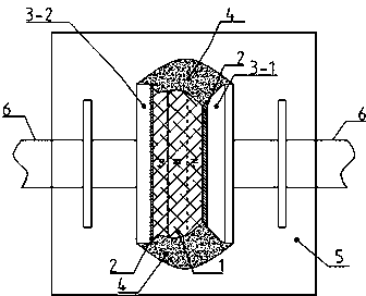
[0016] figure 1 A schematic diagram of the O.J diode structure is shown, which includes a chip 1. The two ends of the chip 1 are welded with solder 2. The lead near the P+ end of the chip is a flat lead 3-2, and the lead connected to the N+ surface of the chip is a tapered lead. 3-1, apply glue 4 on the chip 1 and the end of the lead, encapsulate the chip 1 and the lead with epoxy resin 5 , and provide an electroplating layer 6 on the periphery of the lead.

[0017] The O.J diode key process step of making above-mentioned structure among the present invention is as follows:

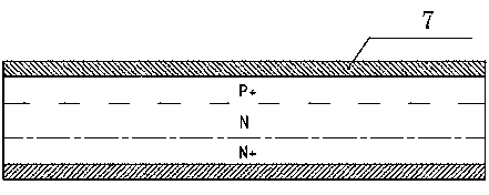
[0018] Coating photoresist: such as figure 2 As shown, after nickel plating is completed on the P+ and N+ surfaces of the silicon wafer, the photoresist 7 is coated on the P+ and N+ surfaces of the silicon wafer to protect the electrode surface during the corrosion process. The thickness of the photoresist is 100~300um.

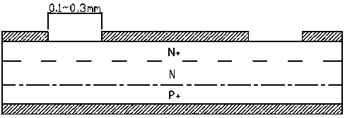
[0019] Lithography: such as image 3 As shown, the N+ surface is photolithograph...


PUM


Abstract

The invention relates to a production process for an O.J diode. The production process is characterized by comprising the following steps: coating photoresist on a silicon wafer after the silicon wafer is plated with nickel; carrying out photo-etching to form a pattern on the N+ surface of the silicon wafer; scribing with the pattern on the N+ surface of the silicon wafer as a reference scribing line; carrying out acid-corroding on the surface of the scribed chip; removing the photoresist from the surface and plating with nickel again; and then, welding, washing with alkali, slivering and carrying out other conventional procedures so as to fabricate the diode. The chip protected by the photoresist is corroded with acid, so that the damage generated on the chip during scribing can be eliminated; after the chip is corroded with acid, the photoresist is removed and the chip is welded, and then, the chip is washed with alkali, so that metal substances in welding materials and lead wires can be prevented from reacting with acid during acid-washing so as to affect the corrosion rate of the chip; and a large number of cleaning processes can be saved, so that resources are saved. In addition, as no metal ions are absorbed on the surface of the chip, faults such as electrical degradation, thermal breakdown at a high temperature and the like of the product can be avoided, and the electrical yield can be increased from the traditional 96% to 98%.

Description

technical field [0001] The invention relates to a diode production process, in particular to an O.J diode production process. Background technique [0002] The traditional PN junction bare diode (Open Junction, referred to as O.J chip) uses a chip (main component: silicon), solder (main component: lead, tin, silver) and leads (main component: copper) for high temperature welding, and then the chip surface pickling treatment. During the pickling process, the metal substances in the solder and the leads will react with the mixed acid, which will affect the corrosion rate of the chip. In addition, the metal ions (or atoms) generated by the reaction of these metals with acid will be attached to the surface of the chip in the form of chemical bonds, and the post-process needs to use a large amount of pure water and chemical reagents for cleaning. Such cleaning not only consumes a lot of resources, but also cannot thoroughly clean the copper atoms attached to the chip surface. ...

Claims


Application Information

Patent Timeline
Patent Type & Authority Patents(China)
IPC IPC(8): H01L21/329
Inventor 赵宇
Owner RUGAO DACHANG ELECTRONICS
Learn More