Method and system of laser scanning phase-microscope imaging

A technology of laser scanning and microscopic imaging, which is applied in the field of optical imaging, can solve problems such as fusion, lack of sample phase information transformation, unfavorable fusion of laser scanning confocal microscopic technology, etc., to shield the impact of imaging quality and simplify the switching process Easy operation, high imaging contrast effect

Inactive Publication Date: 2014-08-20
PEKING UNIV
View PDF4 Cites 0 Cited by
  • Summary
  • Abstract
  • Description
  • Claims
  • Application Information

AI Technical Summary

Problems solved by technology

[0002] Laser scanning confocal microscopy technology uses the pinhole placed in front of the detector to effectively shield the impact of non-focus light on the imaging quality of the sample, and realize the imaging process of point scanning and point detection. The ability to transform information into intensity information, so non-fluorescence-labeled structural imaging of transparent biological samples cannot be performed, and it needs to be fused with other microscopic imaging methods to realize point-by-point scanning / detection methods for transparent biological samples
[0003] The microscopic imaging methods of biological tissue in the prior art mainly include: 1. The differential interference phase contrast microscopic imaging method uses two Wollaston Prisms (Wollaston Prism), a polarizer (Polarizer) and an analyzer (Analyzer), based on Wide-field polarized light is used to image transparent biological tissue, and the imaging result can present the relief-like structure of biological tissue, but the above-mentioned microscopic imaging method needs to add a polarizing element in the optical path to generate polarized light, and use the shear formed by two beams of polarized light Phase differential detection of angles, the components used are expensive and cannot detect samples with birefringence characteristics
At the same time, wide-field imaging requires the use of CCD cameras for data acquisition, so it is not conducive to integration with laser scanning confocal microscopy using point detectors
2. Oblique illumination microscopic imaging method uses Hoffman Modulator and Slit Stop to image transparent biological tissue based on wide-field oblique incident light source, and the imaging result can present biological tissue However, since the optical modulator and slit diaphragm need to be inserted in the optical path of the above microscopic imaging method, it is not conducive to switching between different modes during the experiment, and also because the wide-field imaging requires the use of a CCD camera Data acquisition, so not conducive to integration with laser scanning confocal microscopy with point detectors

Method used


Image

  • Method and system of laser scanning phase-microscope imaging
  • Method and system of laser scanning phase-microscope imaging
  • Method and system of laser scanning phase-microscope imaging

Examples


Embodiment Construction

[0017] The present invention will be described in detail below in conjunction with the accompanying drawings and embodiments.

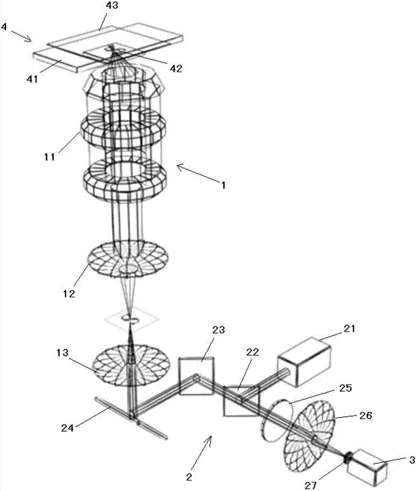
[0018] Such as figure 1As shown, the laser scanning phase microscopy imaging system of the present invention includes a fluorescence microscope 1, a laser confocal scanning system 2 and a photoelectric detection system 3; the fluorescence microscope 1 includes an objective lens 11, a tube mirror 12 and a scanning mirror 13; The focusing scanning system 2 includes a laser 21, a dichroic mirror 22, an X-direction scanning galvanometer 23, a Y-direction scanning galvanometer 24, a filter 25, a converging lens 26, and a pinhole 27; At the light entrance hole of the pinhole 27, the photodetection system 3 is located in the light exit direction of the pinhole 27, and is used to receive the fluorescence transmitted by the biological sample. The laser 21 emits excitation light to the dichroic mirror 22 for reflection or transmission (light splitting), and th...


PUM


Abstract

The invention relates to a method and a system of laser scanning phase-microscope imaging. The system comprises a fluorescence microscope, a laser confocal laser scanning system and a photoelectric detection system, wherein the laser confocal laser scanning system is arranged in a light inlet hole of the fluorescence microscope; the photoelectric detection system is arranged at a light outlet direction of the laser confocal laser scanning system; an angle between each adjacent optical elements is regulated; a sample slice is arranged on a testing table; a fluorescence medium is added on the top of a glass slide; after being focused and in beam expansion through a dichroscope, an X-directional scanning galvanometer, a Y-directional scanning galvanometer, a scanning mirror and a tube lens, exciting light generated by the laser launches to an object lens and is focused on a biological sample; the exciting light focused on the biological sample launches to the fluorescence medium through the biological sample; the fluorescence medium is excited by the exciting light so as to launch fluorescence; the fluorescence shines and returns along the original light path through the biological sample; the emergent fluorescence launches to a filter and is focused through a convergent lens so as to enter a needle hole; the fluorescence exited by the needle hole is received and processed through the photoelectric detection system so as to obtain a relief structure of the biological sample. The method and system provided by the invention can be widely used in an imaging process of the biological sample.

Description

technical field [0001] The invention relates to an optical imaging method and system, in particular to a laser scanning phase microscopic imaging method and system suitable for transparent biological tissue imaging. Background technique [0002] Laser scanning confocal microscopy technology uses the pinhole placed in front of the detector to effectively shield the impact of non-focal plane light on the imaging quality of the sample, and realize the imaging process of point scanning and point detection. The ability to transform information into intensity information, so non-fluorescence-labeled structural imaging of transparent biological samples cannot be performed, and it needs to be fused with other microscopic imaging methods to realize point-by-point scanning / detection methods for transparent biological samples. [0003] The microscopic imaging methods of biological tissue in the prior art mainly include: 1. The differential interference phase contrast microscopic imagin...

Claims


Application Information

Patent Timeline
Patent Type & Authority Patents(China)
IPC IPC(8): G01N21/64G02B21/36
Inventor 丁翼晨谢浩席鹏
Owner PEKING UNIV
Why Eureka
Try Eureka