Separation method for nucleic acid and application thereof
A technology for nucleic acid separation and electrophoresis, applied in the field of bioengineering, to achieve low-cost separation, improved sensitivity and stability, high accuracy and stability
- Summary
- Abstract
- Description
- Claims
- Application Information
AI Technical Summary
Problems solved by technology
Method used
Image

Examples
Embodiment 1
[0125] Embodiment 1. Electrophoresis tank structure
[0126] 1. A separated two-chamber electrophoresis tank
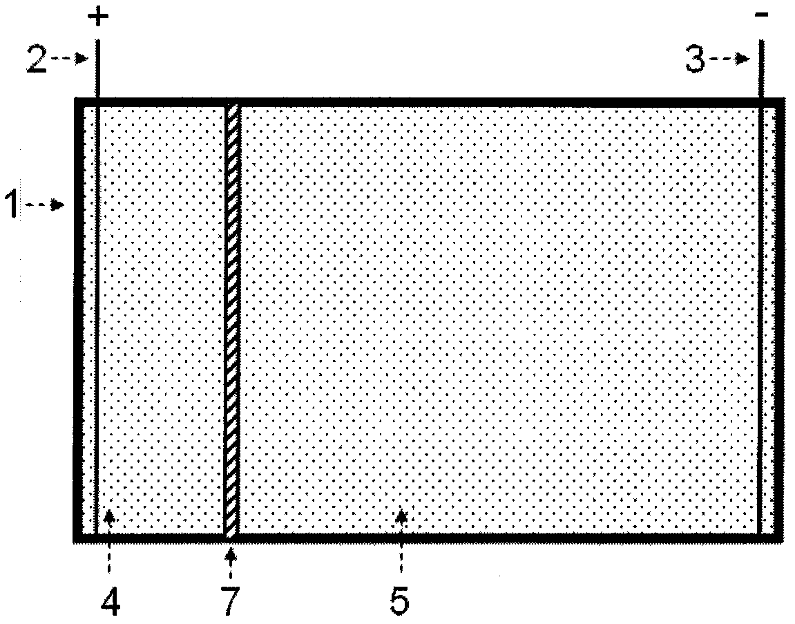
[0127] see figure 1 , the electrophoresis tank includes a tank body 1, an anode 2, a cathode 3, an anode area 4, an intermediate area 5 and an agarose gel partition 7; Zone 4 and intermediate zone 5, anode 2 and cathode 3 are respectively located in these two zones.
[0128] 2. A separated two-chamber electrophoresis tank with selective nucleic acid separation components
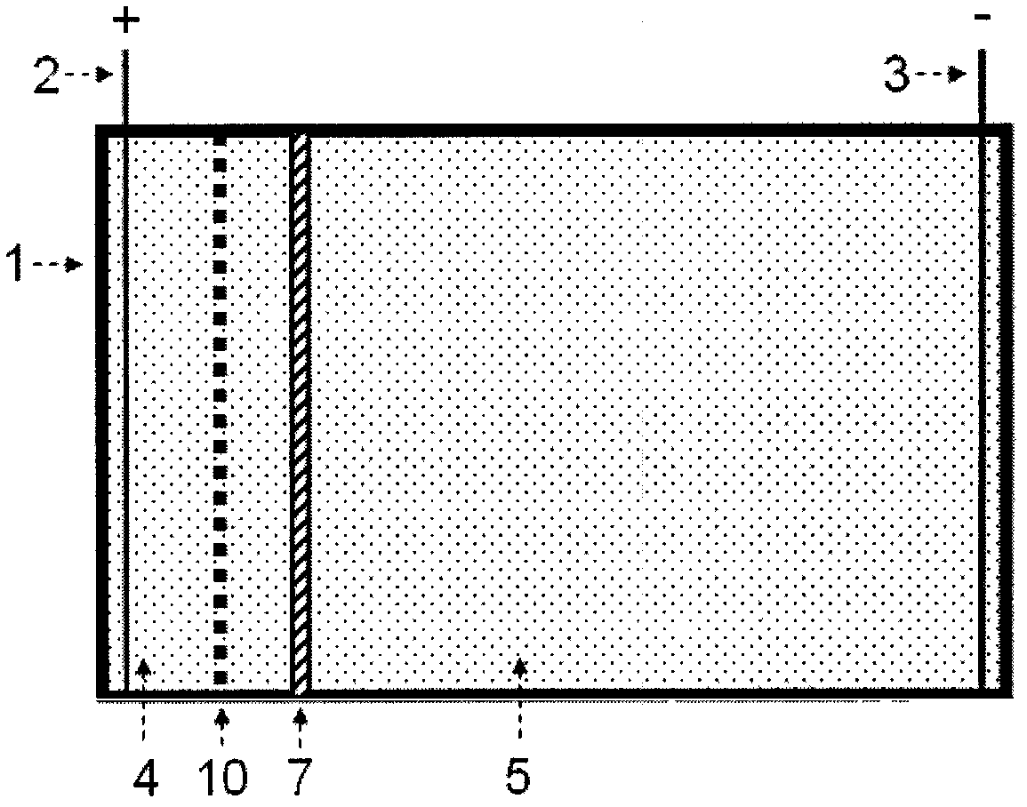
[0129] see figure 2 , the electrophoresis tank includes a tank body 1, an anode 2, a cathode 3, an anode area 4, an intermediate area 5, an agarose gel partition 7 and a selective nucleic acid separation part 10; The two regions separated by the glue partition 7 are the anode region 4 and the middle region 5 respectively, and the anode 2 and the cathode 3 are respectively located in these two regions; the selective nucleic acid separation component 10 is located between the anode region and the...
Embodiment 2
[0142] Example 2. Nucleic acid concentration
[0143] use figure 1 The shown two-chamber electrophoresis cell separated by agarose gel concentrates the nucleic acid components in solution. The volume of the anode area of the electrophoresis tank is 20mL, the volume of the middle area is 200mL, the width of the agarose strip is 1cm, and the top surface exceeds the liquid level height of the electrophoresis buffer by 0.5cm, forming a separation between the anode area and the middle area of the electrophoresis tank .
[0144] 1. Take 20ug of purified pGL3 (Promega) plasmid, dissolve it in 200mL 0.5×TBE, and the final concentration of the plasmid is 100ng / mL;
[0145] 2. Slowly add 200mL of plasmid solution to the middle area of the electrophoresis tank, and add 20mL of 0.5×TBE to the anode area of the electrophoresis tank;
[0146] 3. If figure 1 Connect the power electrodes as shown, and stop the electrophoresis after 20 minutes of electrophoresis at a constant volta...
Embodiment 3
[0150] Example 3. Nucleic acid enrichment based on selective nucleic acid separation components
[0151] use figure 2 A two-chamber electrophoresis cell with selective nucleic acid separation components separated by agarose gel is shown to concentrate nucleic acid components in solution. The volume of the anode area of the electrophoresis tank is 20mL, the volume of the middle area is 200mL, the width of the agarose strip is 1cm, and the top surface exceeds the liquid level height of the electrophoresis buffer by 0.5cm, forming a separation between the anode area and the middle area of the electrophoresis tank . The selective nucleic acid separation component is an activated DEAE cellulose membrane, located in the nucleic acid transfer channel between the anode area and the middle area.
[0152] 1. Activation of DEAE cellulose membrane: Cut a piece of DEAE cellulose membrane (Schleicher & Schuell, NA-45) with a cross-sectional size suitable for the electrophoresis area,...
PUM
| Property | Measurement | Unit |
|---|---|---|
| recovery rate | aaaaa | aaaaa |
Abstract
Description
Claims
Application Information
 - R&D
- Intellectual Property
- Life Sciences
- Materials
- Tech Scout
- Unparalleled Data Quality
- Higher Quality Content
- 60% Fewer Hallucinations
Browse by: Latest US Patents, China's latest patents, Technical Efficacy Thesaurus, Application Domain, Technology Topic, Popular Technical Reports.
© 2025 PatSnap. All rights reserved.Legal|Privacy policy|Modern Slavery Act Transparency Statement|Sitemap|About US| Contact US: help@patsnap.com