
Water spray propulsion unit for ship

A water-jet propulsion, marine technology, applied in ship propulsion, propulsion components, ship construction, etc., can solve the problems of large impeller size, no self-priming ability, large thrust, etc., to ensure stability and maneuverability , The effect of diverse placement positions and enhanced slewing performance

Active Publication Date: 2012-11-28
徐世友
View PDF7 Cites 15 Cited by
  • Summary
  • Abstract
  • Description
  • Claims
  • Application Information

AI Technical Summary

Problems solved by technology

[0003] One is that the efficiency is low. The propeller relies on the high-speed rotation of the impeller to generate force on the water. The high-speed rotation of the impeller produces axial force and radial force (centrifugal force). The axial force makes the water flow move in the axial direction and propel the ship. The radial force hardly produces a propulsion effect on the ship, the radial force is actually a useless torque, and it does useless work.
[0004] The second is that when the speed is high, the impeller of the propeller is in periodic changes in the angle of attack and load, and friction with the water body, which is prone to cavitation effects, resulting in cavitation and cavitation (cavitation erosion), accompanied by noise and water excitation, resulting in a loss of efficiency and seriously affecting safety and stability
Water jet propulsion is less efficient than propellers at low ship speeds (especially below 20 knots)
[0008] Second, it is difficult to further increase the propulsion force. To increase the propulsion force, on the one hand, it is necessary to increase the output power of the motor (usually gasoline engine, diesel engine), and on the other hand, it is necessary to increase the size and speed of the impeller of the axial flow pump. Large size The impeller is difficult to process, and due to the limitation of the installation space, the volume and weight of the axial flow pump cannot be too large, and after the size of the impeller increases and the speed increases, although the flow rate and lift will increase, the friction between the impeller and water will cause The cavitation effect and cavitation phenomenon will increase significantly, and the noise and excitation will also become obvious, so it is difficult for the water jet propulsion pump to realize the ultra-high speed sailing of the ship, especially when it is higher than 50 knots, the efficiency of water jet propulsion will significantly reduce
[0009] Third, it is difficult to achieve gas-liquid two-phase co-spraying. The latest research shows that the most ideal water jet propulsion should be gas-liquid two-phase co-spraying. The pressurized gas and liquid are mixed in a certain proportion to produce the strongest thrust. , the main reason is that after the high-pressure gas is ejected from the nozzle, the volume expands rapidly and ruptures, producing a large impact force. This impact force and the ejected water flow form a gas-water blended fluid with a high velocity and a high density. , The quality is different from the surrounding seawater, forming a stable flow field that is different from the surrounding seawater, and will not be mixed with the surrounding seawater, so the thrust is very huge, and it also has the ability to resist wind and waves, while the axial flow pump is not suitable for pressurized transportation gas-liquid two-phase fluid
The efficiency only reaches the maximum value at the head flow design point, deviates from the efficiency point, and the efficiency drops sharply. The disadvantages of the centrifugal pump are: low head, no self-priming ability, and gas binding phenomenon, which is not suitable for pressurized transportation of gas and liquid. phase fluid
[0011] 1. The flow and head characteristic curves are too steep, and the high-efficiency working range is too narrow to adapt to a wide speed range.
[0012] 2. It is difficult to increase the size of the impeller. On the one hand, it is limited by the processing technology, and on the other hand, it is limited by the significant increase of cavitation effect and cavitation phenomenon, so it is impossible to achieve high thrust.
[0013] 3. It is difficult to achieve gas-liquid two-phase blending and co-spraying
[0014] Due to the dual constraints of structural size and cavitation performance, various existing water jet propulsion pumps cannot adapt to the development requirements of large-scale, high-speed, high-performance, low-noise, low-fuel consumption, easy-to-control, and wide-speed range of ships. Therefore be badly in need of developing a kind of brand-new marine water jet propulsion device

Method used


Image

  • Water spray propulsion unit for ship
  • Water spray propulsion unit for ship
  • Water spray propulsion unit for ship

Examples


Embodiment Construction

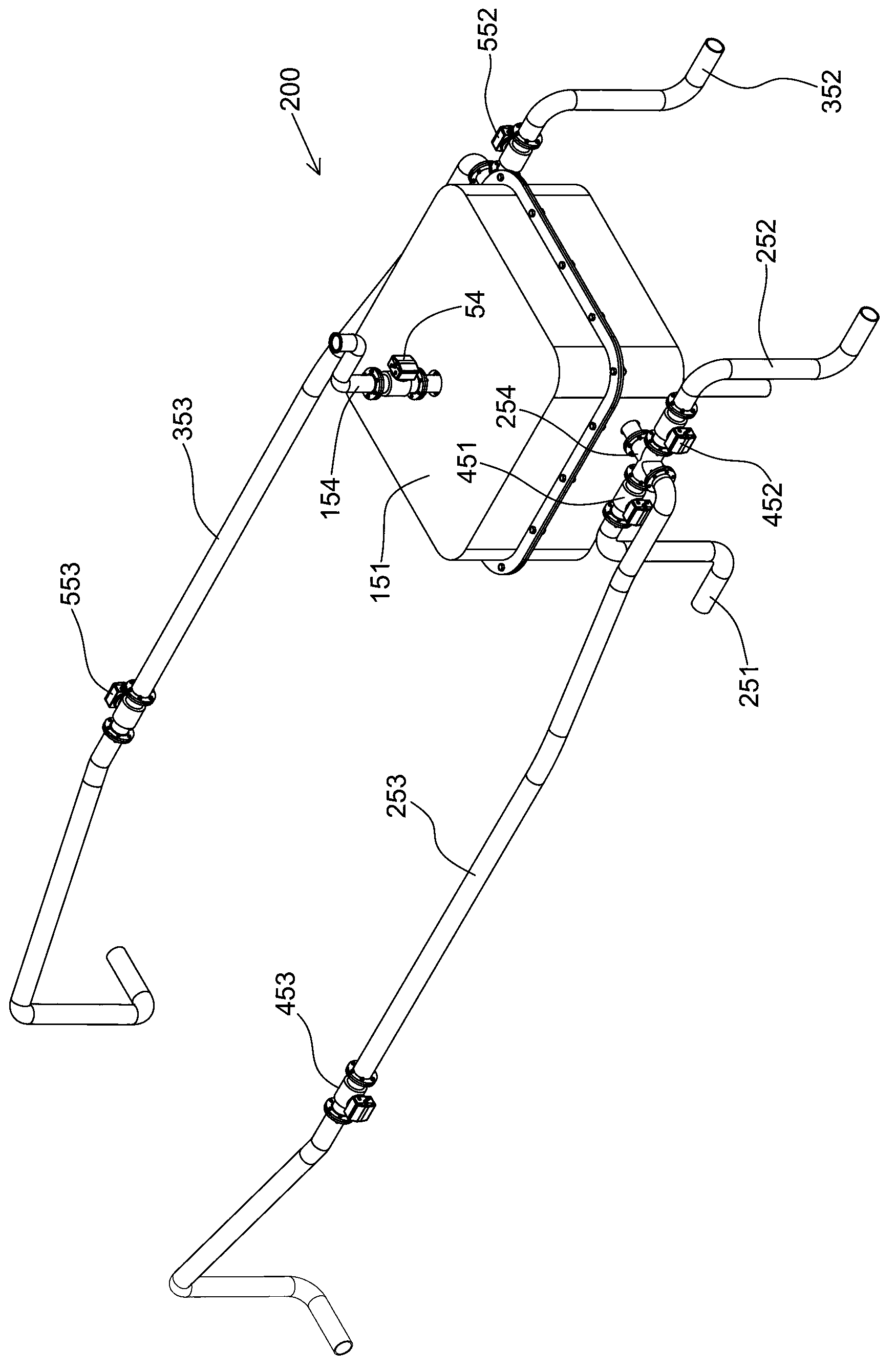
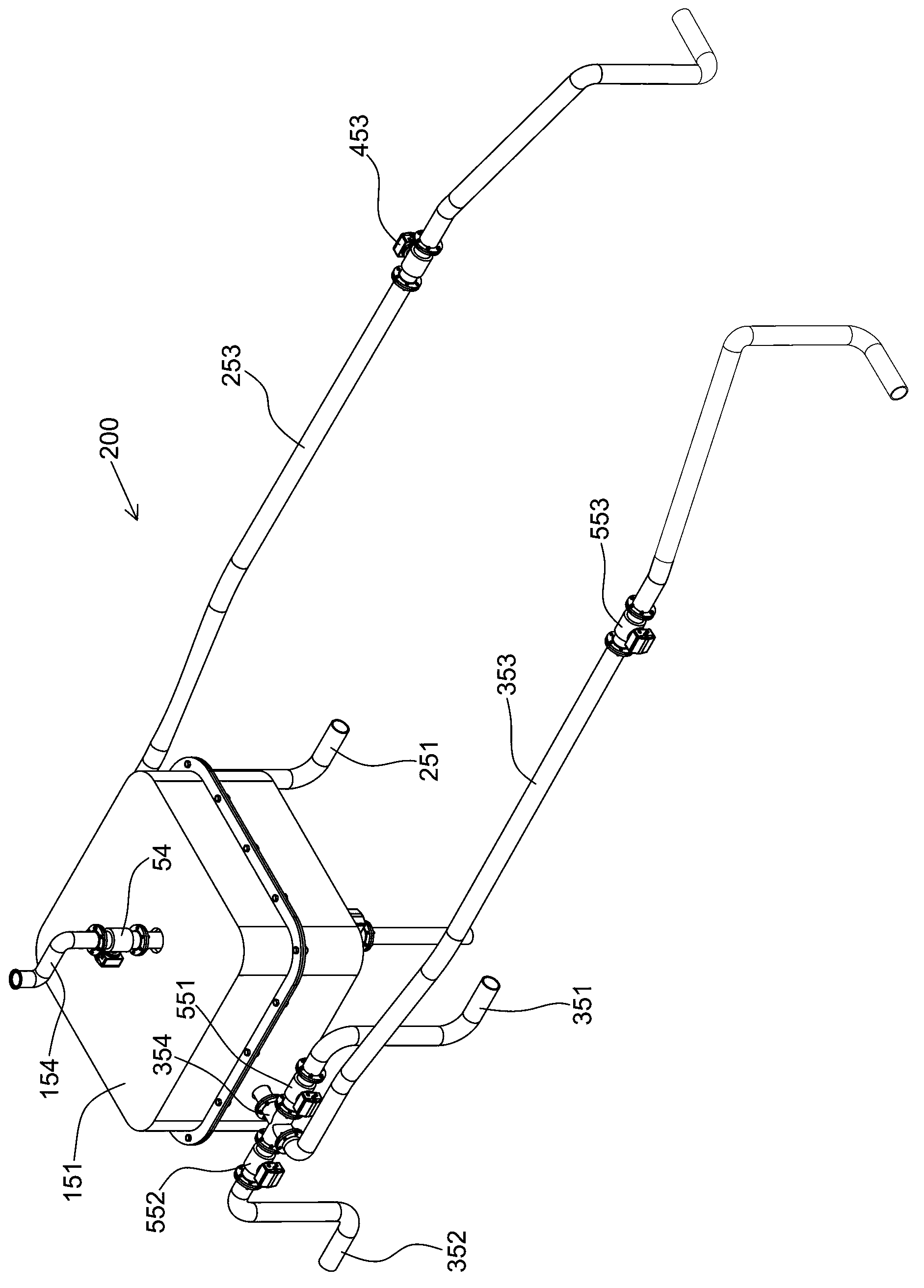
[0083] Label in the figure

[0084] 1 pump body 2 pump body 3 pump body 4 pump body

[0085] 5 Partition plate assembly 6 Front end cover assembly 7 Rear end cover assembly

[0086]8 central axis 801 front axle head 802 rear axle head

[0087] 9 magazines 901 opening 902 opening

[0088] 900 peripheral flange 10 shell

[0089] 101 side flange 102 side flange 103 bottom flange

[0090] 11 Eccentric sleeve 111 Eccentric hole 112 Keyway

[0091] 12 rotor 120C-shaped notch groove 121 center hole

[0092] 122 front bearing chamber 123 rear bearing chamber 124 front bearing 125 rear bearing

[0093] 13 baffle plate 131 upper limit shaft 132 lower limit shaft

[0094] 14 Piston 140V-shaped notch groove 15 Working chamber

[0095] 151 chassis 152 motor 153 liquid inlet pipe

[0096] 154 intake pipe 155 rotary positive displacement pump 156 storage battery

[0097] 157 belt pulley 158 belt pulley 159 transmission belt 16 piston cavity

[0098] 17 fluid input channel 171 upst...


PUM


Abstract

The invention relates to a water spray propulsion unit for a ship, consisting of a case, a motor, a liquid inlet tube, a gas inlet tube, a rotation type volume pump and six nozzles. The six nozzles are respectively a left forward nozzle, a left backward nozzle, a left lateral nozzle, a right forward nozzle, a right backward nozzle and a right lateral nozzle, wherein the left forward nozzle and the left backward nozzle are installed at the left side of the tail part of the ship body; the right forward nozzle and the right backward nozzle are installed at the right side of the tail part of the ship body; the left lateral nozzle is installed at the left side of the front part of the ship body; and the right lateral nozzle is installed at the right side of the front part of the ship body. A dynamic shaft of the motor is connected with a central shaft of the rotation type volume pump through a decelerating mechanism, the liquid inlet tube is connected with a liquid inlet tube connector of the rotation type volume pump, and the gas inlet tube is connected with a gas inlet tube connector of the rotation type volume pump. By taking the rotation type volume pump as a core part, the water spray propulsion unit for the ship has the advantages of small volume, light weight, high flow, high lift and great suction, and the problems of cavitation and cavitation erosion of a vane pump are effectively solved. According to the water spray propulsion unit, gas-liquid two-phase propulsion is adopted so that the propulsion efficiency is high.

Description

technical field [0001] The invention relates to a ship propulsion device, in particular to a gas-liquid two-phase propulsion ship propulsion device. Background technique [0002] Ship propulsion devices are mainly divided into two categories, one is the propeller and the other is the water jet propulsion device. As a traditional propulsion device, the propeller mainly has two problems: [0003] One is that the efficiency is low. The propeller relies on the high-speed rotation of the impeller to generate force on the water. The high-speed rotation of the impeller produces axial force and radial force (centrifugal force). The axial force makes the water flow move in the axial direction and propel the ship. The radial force hardly produces a propulsion effect on the ship, the radial force is actually a useless torque, and it does useless work. [0004] The second is that when the speed is high, the impeller of the propeller is in periodic changes in the angle of attack and loa...

Claims


Application Information

Patent Timeline
Patent Type & Authority Applications(China)
IPC IPC(8): B63H11/08F04C2/44
Inventor 王海军陈洪亮
Owner 徐世友
Learn More