Movable contact member and switch device using movable contact member
A technology of moving contacts and components, which is applied in the field of movable contact parts and switch devices, can solve the problems of insufficient travel, reduced switch life, and inability to realize miniaturization of switch devices, etc., to achieve long travel, prolong life, and suppress The effect of the crack
- Summary
- Abstract
- Description
- Claims
- Application Information
AI Technical Summary
Problems solved by technology
Method used
Image
Examples
no. 1 approach
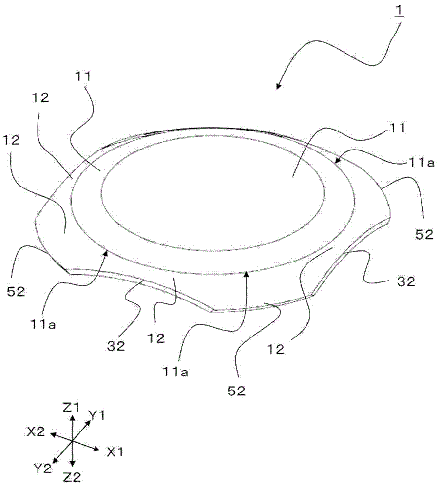
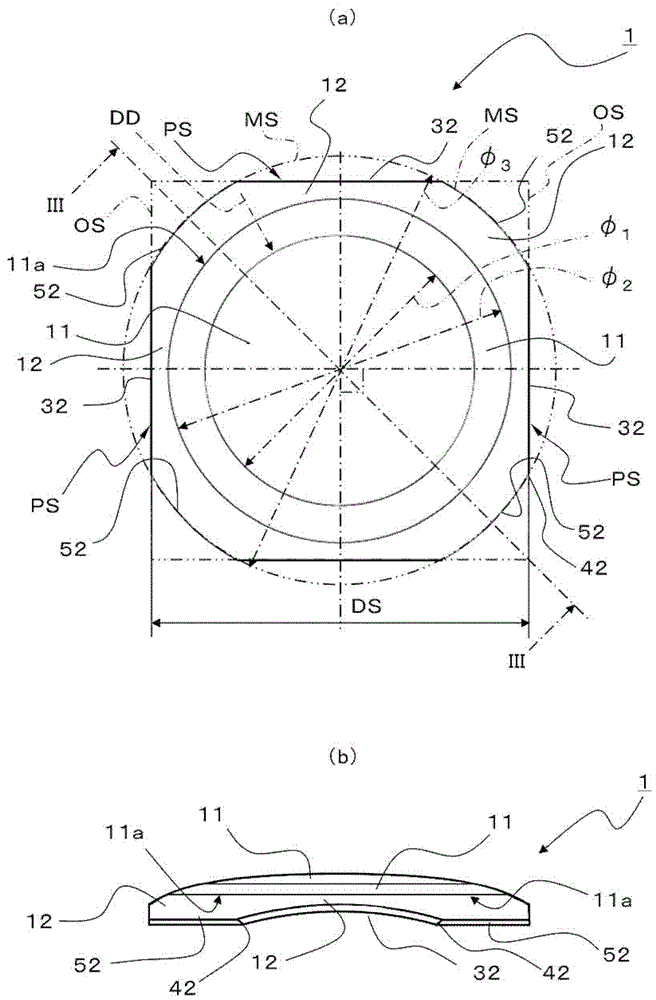
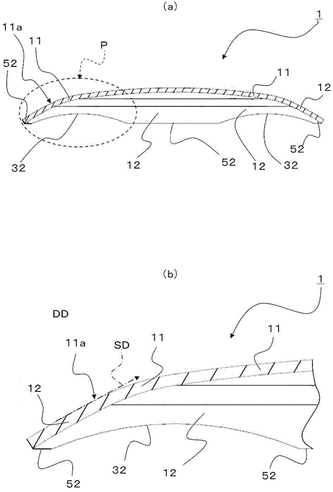
[0046] figure 1 It is a perspective view explaining the movable contact member 1 of the first embodiment of the present invention. figure 2 It is a figure explaining the movable contact member 1 of 1st Embodiment of this invention, figure 2 (a) is a plan view, figure 2 (b) is a side view. image 3 It is a figure explaining the movable contact member 1 of 1st Embodiment of this invention, image 3 (a) is figure 2 (a) The cross-sectional view of line III-III shown in (a), image 3 (b) is image 3 (a) An enlarged cross-sectional view of part P shown in (a).
[0047] Such as figure 1 As shown, the movable contact member 1 is configured to include: a bulging portion 11 formed of a conductive metal plate, which can be reversed by pressing; formed continuously. Thereby, since the skirt part 12 is formed continuously with the outer peripheral edge part 11a of the bulging part 11, it becomes the structure which supports the bulging part 11. As shown in FIG.
[0048] Suc...
no. 2 approach
[0063] Figure 4 It is a perspective view explaining the switch device 201 of 2nd Embodiment of this invention. Figure 5 It is an exploded perspective view illustrating the switch device 201 according to the second embodiment of the present invention. Image 6 is a diagram illustrating a switch device 201 according to a second embodiment of the present invention, Image 6 (a) is a top view of the switch base 4, Image 6 (b) is a plan view in which the movable contact member 1 is placed on the switch base 4 . In addition, the same code|symbol is attached|subjected to the same structure as 1st Embodiment, and detailed description is abbreviate|omitted.
[0064] Such as Figure 4 to Figure 6 As shown, the switch device 201 according to the second embodiment of the present invention is configured to include: the movable contact member 1 according to the first embodiment of the present invention; the switch base 4 having a housing portion 14 for receiving the movable contact mem...
Deformed example 1
[0074] In the above-described embodiment, the grounding portion of the contact portion 52 of the movable contact member 1 is configured to be linearly inclined, but it may be as follows: Figure 7 As shown in (a), the ground portion of the contact portion C62 is bent. Therefore, it is possible to reduce the wear of the peripheral fixed contacts 5 and the contact portion C62 caused by the repeated inversion operation of the movable contact member C11. Thereby, the lifetime of a switch device can be extended further.
PUM
 Abstract
Description
Claims
Application Information
 - R&D Engineer
- R&D Manager
- IP Professional
- Industry Leading Data Capabilities
- Powerful AI technology
- Patent DNA Extraction
Browse by: Latest US Patents, China's latest patents, Technical Efficacy Thesaurus, Application Domain, Technology Topic, Popular Technical Reports.
© 2024 PatSnap. All rights reserved.Legal|Privacy policy|Modern Slavery Act Transparency Statement|Sitemap|About US| Contact US: help@patsnap.com


