
Liquid phase connected die forging integral forming method of material

A liquid phase connection and die forging technology, which is applied in welding equipment, non-electric welding equipment, metal processing equipment, etc., can solve the problems of difficult material connection and low strength, and achieve the improvement of physical and chemical properties of the interface, high performance and low forming temperature Effect

Active Publication Date: 2012-10-17
HARBIN INST OF TECH
View PDF5 Cites 6 Cited by
  • Summary
  • Abstract
  • Description
  • Claims
  • Application Information

AI Technical Summary

Problems solved by technology

[0005] The present invention aims to solve the technical problems of difficult material connection and low strength in the existing material connection method, and provides a material liquid phase connection die forging integrated forming method

Method used

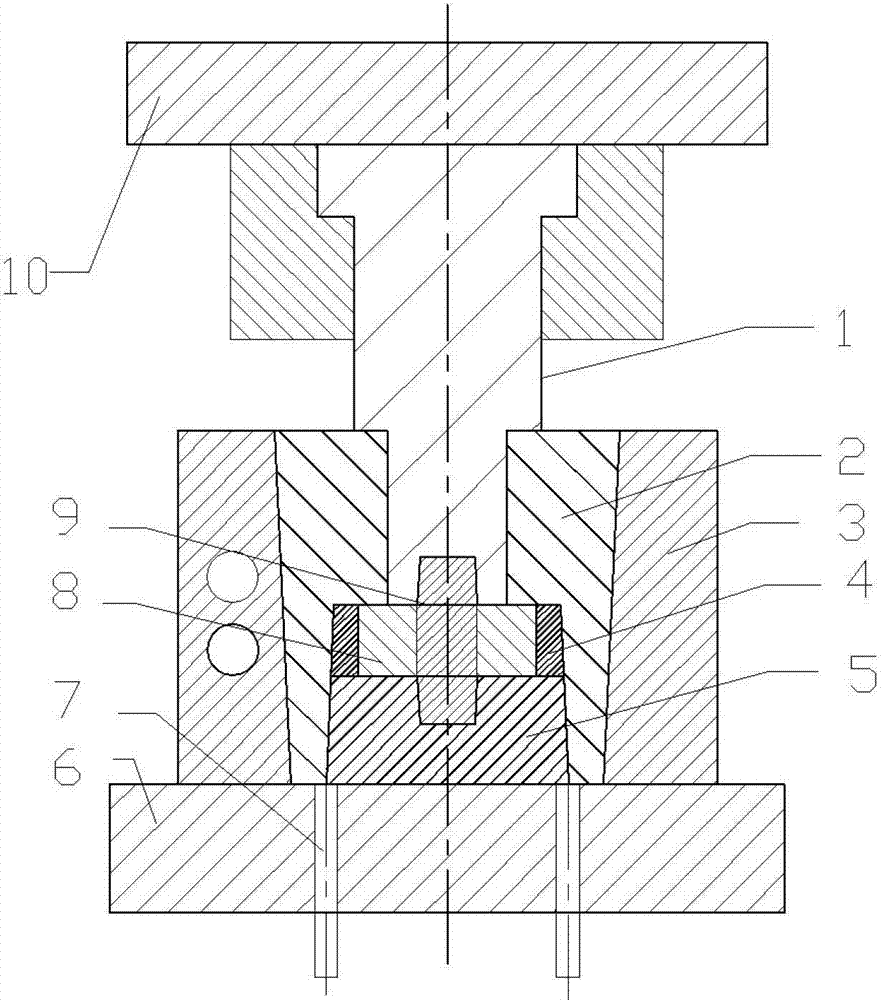
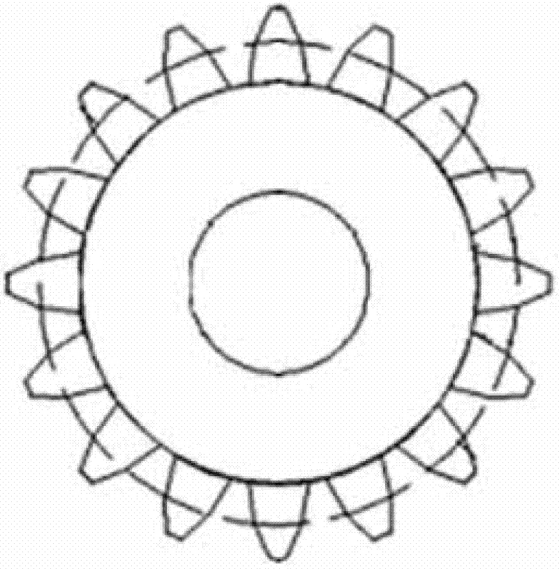
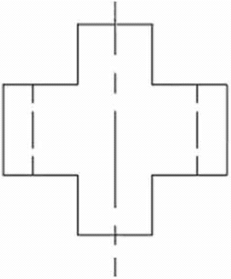

Image

  • Liquid phase connected die forging integral forming method of material
  • Liquid phase connected die forging integral forming method of material
  • Liquid phase connected die forging integral forming method of material

Examples


specific Embodiment approach 1

[0016] Specific implementation mode 1: In this implementation mode, a material liquid phase connection die forging integrated forming method is carried out according to the following steps:

[0017] 1. Remove oil and impurities from the surfaces to be connected of the materials to be connected;

[0018] 2. Heat the materials to be connected after step 1 to their plastic deformation temperature under the protection of vacuum or inert gas, and keep them warm until the temperature of each part of the materials is consistent; continue heating to make the temperature of the materials to be connected rise rapidly. to their melting point temperature and keep warm to melt the surface of the material;

[0019] 3. Place the material to be connected processed in step 2 in the cavity of the hot press for hot pressing, or place the material to be connected in step 2 between the rolls of the roller machine for roll forming to complete the material liquid Connected die forging integrated fo...

specific Embodiment approach 2

[0022] Embodiment 2: This embodiment differs from Embodiment 1 in that the materials to be connected in step 1 are metal and metal, metal and composite material, or composite material and composite material. Others are the same as in the first embodiment.

[0023] In this embodiment, the materials to be connected may be the same or different, that is, the same material or different materials.

specific Embodiment approach 3

[0024] Embodiment 3: The difference between this embodiment and Embodiment 1 or 2 is that the inert gas in step 2 is nitrogen or argon. Others are the same as in the first or second embodiment.


PUM

PropertyMeasurementUnit
Thicknessaaaaaaaaaa
Finenessaaaaaaaaaa

Abstract

The invention discloses an aluminium alloy and an aluminium alloy composite liquid phase connected die forging integral forming method of a material, and relates to a material forming method. The technical problems of difficulty in connection and low intensity in the conventional material connection method are solved. The method comprises the following steps of: removing oil stains and impurities on the surface to be connected of the material to be connected; 2, respecting heating the materials to be connected which processed in the first step to a plastic deformation temperature under the protection of vacuum or inert gas, and keeping the temperature until the temperature of all parts of the materials are consistent; and continuously heating to ensure that the temperature of the material to be connected is quickly raised to a melting point temperature and is kept to melt the surface layer of the material; and 3, placing the material to be connected which is treated in the second step into a die cavity of a hot press for hot-pressing formation, or placing the material to be connected between rollers of a rolling machine for performing rolling formation so as to finish the liquid phase connected die forging integral formation of the material. A joint prepared by the method can be applied to the fields of aerospaces, space technology, nuclear industry, micro-electrons, automobiles and petrochemical industry.

Description

technical field [0001] The invention relates to a material forming method. Background technique [0002] Material connection is to connect two or more materials (including metals and non-metals, composite materials, compounds, etc.) together through certain process conditions to form a complete structure with certain performance. The material connection structure has the excellent properties of various materials, so it has been widely used in aerospace, space technology, nuclear industry, microelectronics, automobile, petrochemical and other fields. The progress of modern science and technology has increasingly increased the requirements for material science and engineering technology. The development of new high-performance structural parts and advanced connection technology has become an urgent problem for high-tech enterprises. areas are more evident. For example, the heat pipe structure in the aerospace field and the national production field adopts the plate and tube ...

Claims


Application Information

Patent Timeline
IPC IPC(8): B23K20/02B23K20/04B23K20/24
Inventor 程远胜马卓识
Owner HARBIN INST OF TECH
Learn More