
Method and device for improving room temperature plasticity of block amorphous alloy and structural member of block amorphous alloy

A technology of amorphous alloys and structural parts, applied in the field of advanced materials, can solve problems such as long time-consuming, complicated processing, and inability to adapt to shapes, etc., and achieve the effects of short processing time, simple process, and high rigidity

Inactive Publication Date: 2012-10-10
SHANDONG UNIV
View PDF2 Cites 9 Cited by
  • Summary
  • Abstract
  • Description
  • Claims
  • Application Information

AI Technical Summary

Problems solved by technology

Obviously, the above post-processing methods are not suitable for bulk amorphous alloys and their structural parts with complex shapes, and the processing process is complicated and time-consuming

Method used


Image

  • Method and device for improving room temperature plasticity of block amorphous alloy and structural member of block amorphous alloy
  • Method and device for improving room temperature plasticity of block amorphous alloy and structural member of block amorphous alloy
  • Method and device for improving room temperature plasticity of block amorphous alloy and structural member of block amorphous alloy

Examples


Embodiment 1

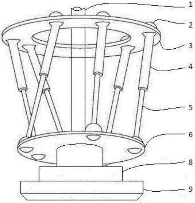
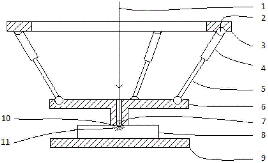
[0043] Use the above-mentioned device to polish the surface of the Zr35Ti30Cu8.25Be26.75 amorphous alloy body with a size of 33.5mm×3mm×1.5mm rectangular cross-section beam and place it on a rigid backing plate. The boss of the center hole, the boss is arranged along the surface normal direction of the amorphous alloy body, and presses the surface, the diameter of the center hole of the boss is 2mm;

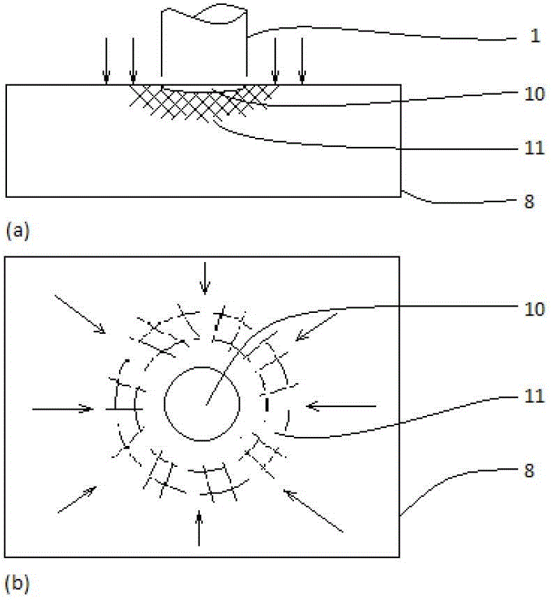
[0044] Pass a short pulse laser beam to the center hole of the boss, the pulse width of the laser beam is 11ns, and the maximum power density is 8GW / cm 2 , irradiate the surface of the amorphous alloy body to generate explosive plasma shock waves, and the shock wave acts on the amorphous alloy body, causing a small amount of high strain rate plastic deformation in the irradiated area, forming micro pits, and the plastic deformation will be constrained by the boss At the same time, it is also constrained by the surrounding undeformed area, so it is carried out under the state of t...

Embodiment 2

[0047] Use the above-mentioned device to polish the surface of an amorphous alloy body with a rectangular cross-section beam shape of 33.5mm×3mm×1.5mm and place it on a rigid backing plate. The amorphous alloy material is Zr41.2Ti13.8Cu12.5Ni10Be22.5. Place an inverted boss with a central hole on the amorphous alloy body, the boss is set along the surface normal of the amorphous alloy body, and press the surface, the diameter of the center hole of the boss is 2mm;

[0048] Pass a short pulse laser beam to the center hole of the boss, the pulse width of the laser beam is 11ns, and the maximum power density is 8GW / cm 2 , irradiate the surface of the amorphous alloy body to generate explosive plasma shock waves, and the shock wave acts on the amorphous alloy body, causing a small amount of high strain rate plastic deformation in the irradiated area, forming micro pits, and the plastic deformation will be constrained by the boss At the same time, it is also constrained by the surr...


PUM


Abstract

The invention relates to a method and a device for improving room temperature plasticity of block amorphous alloy and the structural member of the block amorphous alloy. The method comprises the following steps of: polishing and smoothening the surface of an amorphous alloy body and placing the polished amorphous alloy body on a rigid cushioning plate; introducing short-pulse laser beams to the surface of the polished amorphous alloy body through a boss with a center hole to generate explosion plasma impact waves which act on the amorphous alloy body so that an irradiated region generates trace high-strain-rate plastic deformation and compact shearing zone and residual compressive stress are formed. According to the invention, multiple mechanical and materialogical mechanisms for improving the room temperature plasticity of the amorphous alloy are compressively utilized, thus the plasticizing effect is obvious, and the method and the device are suitable for various amorphous alloy materials.

Description

technical field [0001] The invention relates to a method and a device for improving the plasticity of an amorphous alloy, in particular to a method and a device for improving the plasticity of a bulk amorphous alloy and its structural parts at room temperature, and belongs to the technical field of advanced materials. Background technique [0002] The high strength, high elastic limit, high corrosion resistance and wear resistance, excellent magnetic properties and isotropy of performance of amorphous alloy make it the most widely used in military, aerospace, marine, electric power, micro-electromechanical systems and other fields. A promising new class of metal-based materials. However, in the unique homogeneous amorphous structure of amorphous alloys, there is a lack of ordered atomic crystal planes and dislocations, resulting in very limited macroscopic room temperature plasticity and becoming a key bottleneck restricting its engineering applications and forming manufactu...

Claims


Application Information

Patent Timeline
IPC IPC(8): C21D1/09C22F3/00
Inventor 季忠刘韧郑超秦绪波
Owner SHANDONG UNIV
Learn More