Light guide plate, surface illuminating device, and liquid crystal display device
A technology of light guide plate and light exit surface, which is applied in the field of light guide plate to achieve the effect of thinning, narrowing interval and high utilization efficiency
- Summary
- Abstract
- Description
- Claims
- Application Information
AI Technical Summary
Problems solved by technology
Method used
Image
Examples
example 1
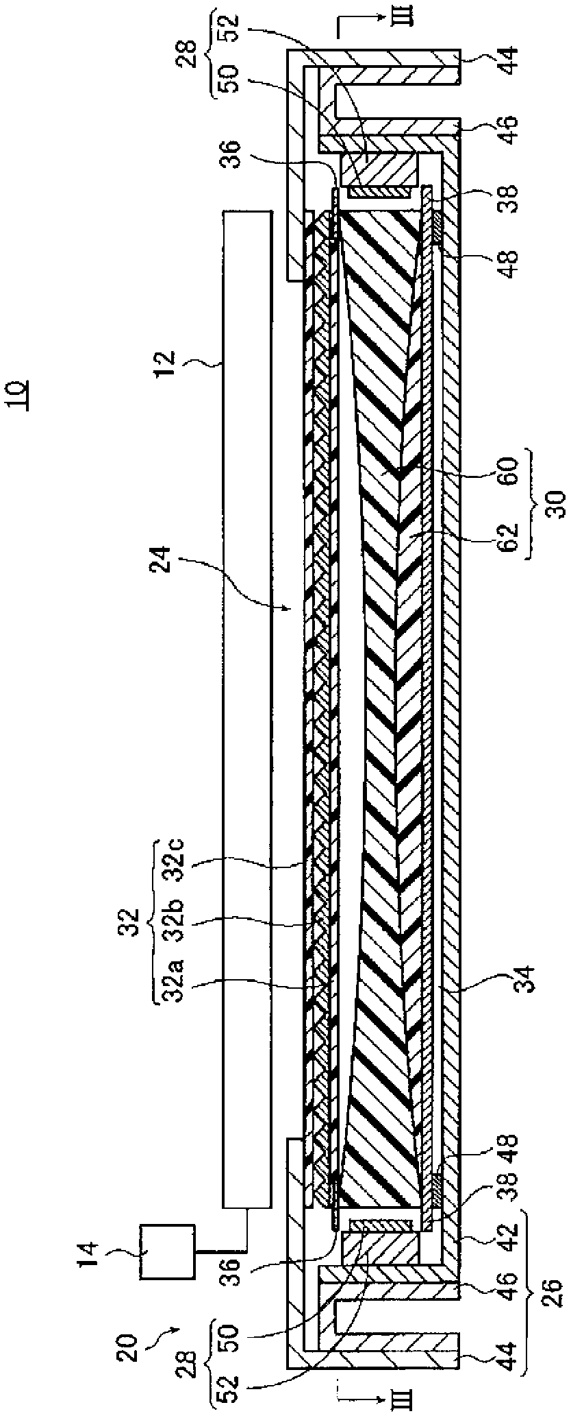
[0192] The light guide plate 30 when the screen size corresponds to 42 is used as Example 1. Specifically, a light guide plate whose length from the first light incident surface 30c to the second light incident surface 30d is set to 545 mm and whose length from the light exit surface 30a to the back surface 30b at the bisector α is The length until the length, that is, the thickness D of the thinnest part is set as 2.56mm, the thickness of the first light incident surface 30c and the second light incident surface 30d, that is, the thickness of the thickest part is set as 3.0mm, and the thickness of the first light incident surface 30c and the second light incident surface 30d is set as 3.0mm. The length from the light exit surface 30a to the boundary surface z at the bisector α of the first layer 60, that is, the thickness D1 of the first layer 60 at the thinnest part of the first layer 60 is set to 2.12 mm, and the second The length from the boundary surface z to the rear sur...
example 2
[0213] As Example 2, the following light guide plate 80 is used. This light guide plate 80 is a light guide plate with the same shape as Example 1 and a screen size of 46, such as Figure 9 As shown, the boundary surface z between the first layer 60 and the second layer 62 is from the second layer 62 from the light exit surface 30a at the bisector α (that is, the central part of the light exit surface) to the first light incident surface. 30c and the second light incident surface 30d become thinner and change continuously, and in the vicinity of the first light incident surface 30c and the second light incident surface 30d, it becomes thicker again toward the light exit surface 30a side. change. At this time, the synthetic particle concentration is obtained using the reverse bias concentration, and the thicknesses (shape of the boundary surface z) of the first layer 60 and the second layer 62 are obtained from the obtained synthetic particle concentration.
[0214] That is, t...
example 3
[0226] As example 3, Figure 9 The light guide plate 80 shown is a light guide plate when the screen size is 32, and the curvature radius R of the concave and convex curved surfaces of the boundary surface z is changed y1 , R y2 , and the particle concentrations of the first layer 60 and the second layer 62 are measured.
[0227] Specifically, the following light guide plate is used as Example 3. The length of the light guide plate from the first light incident surface 30c to the second light incident surface is set to 413mm, and the first light incident surface 30c and the second light incident surface 30d The thickness, that is, the thickness D2 of the thickest part is set to 3mm, the amount of depression d is set to 0.5mm, the radius of curvature of the light exit surface 30a is set to 42500mm, and the thickness D3 of the second layer 62 in the first light incident surface The thickness D4 of the thinnest part of the second layer 62 was 0.5 mm, and the thickness D5 of the...
PUM
| Property | Measurement | Unit |
|---|---|---|
| thickness | aaaaa | aaaaa |
| thickness | aaaaa | aaaaa |
| thickness | aaaaa | aaaaa |
Abstract
Description
Claims
Application Information
 - R&D
- Intellectual Property
- Life Sciences
- Materials
- Tech Scout
- Unparalleled Data Quality
- Higher Quality Content
- 60% Fewer Hallucinations
Browse by: Latest US Patents, China's latest patents, Technical Efficacy Thesaurus, Application Domain, Technology Topic, Popular Technical Reports.
© 2025 PatSnap. All rights reserved.Legal|Privacy policy|Modern Slavery Act Transparency Statement|Sitemap|About US| Contact US: help@patsnap.com


