
Method for determination of inorganic element in fuel gas

An inorganic element and gas technology, which is used in measuring devices, material analysis by electromagnetic means, instruments, etc., can solve the problems of low detection sensitivity of non-metallic elements, cumbersome operation, hindering application and development, etc., to meet the requirements of detection and research. needs, low operating costs, and the effect of easy promotion

Active Publication Date: 2014-03-26
TSINGHUA UNIV
View PDF3 Cites 0 Cited by
  • Summary
  • Abstract
  • Description
  • Claims
  • Application Information

AI Technical Summary

Problems solved by technology

These methods have played an important role in the analysis of inorganic elements, but some of their shortcomings also hinder their own application and development
The atomic absorption method cannot detect inorganic elements at the same time, and the light source needs to be replaced every time an element is detected, which is cumbersome to operate
Inductively Coupled Plasma-Atomic Emission Spectrometry is not Sensitive to Some Nonmetallic Elements
Inductively coupled plasma-mass spectrometry, expensive instruments, high analysis costs, not conducive to popularization, and not suitable for the detection of some non-metallic elements
Although ion chromatography has made outstanding contributions to the detection of non-metallic elements, its analysis time is long, the sensitivity is often not up to the detection requirements under trace conditions, and complex sample pre-concentration steps are required
In addition, Rupp et al. (Anal.Chem., 2010, 82, 6315-6317) used gas chromatography-mass spectrometry to detect trace Hg, AsH 3 ,PH 3 and H 2 However, this method is only suitable for the detection of some volatile inorganic elements, and cannot detect most inorganic elements, especially metal elements.

Method used


Image

  • Method for determination of inorganic element in fuel gas
  • Method for determination of inorganic element in fuel gas
  • Method for determination of inorganic element in fuel gas

Examples


Embodiment 1

[0047] 1. Sample collection:

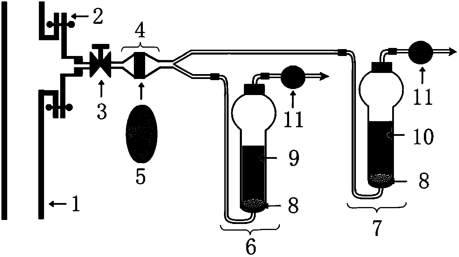
[0048] The gas is collected by using a double-flow path gas-liquid absorption device, and the diameter of the filter membrane is 45mm. At a flow rate of 400mL / min, collect for 90min. The cation absorption bottle contains 6mL of 50mmol / L boric acid solution (used to absorb soluble cations in gas). The anion absorption bottle contains 6mL of 50mmol / L sodium hydroxide solution (used to absorb soluble anions in gas).

[0049] 2. Sample treatment: Divide the collected sample filter membrane into two halves, cut one half into pieces, add 6 mL of analytically pure nitric acid, and put it into a microwave instrument for microwave-assisted digestion. Pour the digested solution into a polytetrafluoroethylene bottle, add the sample containing 50mmol / L boric acid absorption solution, mix well and make up to volume (12ml), and filter it through a 0.45μm membrane for inorganic cation analysis; cut the other half After crushing, add 6mL double-distilled wate...


PUM

PropertyMeasurementUnit
diameteraaaaaaaaaa

Abstract

The invention provides a method for determination of inorganic element in fuel gas, comprising the following steps: sample collection: the fuel gas is divided into two parts so as to flow through cation absorption liquid and anion absorption liquid respectively after the fuel gas flows through a filter membrance; sample handling: the filter membrance is equally divided into two parts, one part of the filter membrance is dispelled by acid liquor, then the cation absorption liquid is added, and through metered volume and filtering, filtrate for cation analysis is obtained, and the other part of the filter membrance is extracted with water, then the anion absorption liquid is added into the extract liquor, and through metered volume and filtering, filtrate for anion analysis is obtained; sample analysis: above filtrates are respectively subsjected to capillary electrophoresis test, and then data is treated. According to the method and the device provided by the invention, the defects of low efficiency, long consuming time, higher analytical cost and difficult in popularizing in traditional method are overcame. The aim to quick test multiple inorganic elements is realized, the operation cost is lower, the operation is simple, and the method is convenient to popularize.

Description

technical field [0001] The invention belongs to the field of chemical analysis and testing, and in particular relates to a rapid determination method for inorganic elements in gas. Background technique [0002] Due to the influence of formation and environment, the gas often contains different concentrations of inorganic elements. These inorganic elements exist in the form of small solid particles, mist and gas. When these inorganic elements settle and adhere to or permeate on the surface of various equipment, components and materials used in the gas industry, it will cause hazards such as metal corrosion and material aging. However, there is no mature collection device and determination method for inorganic elements in gas so far. [0003] At present, the methods of collecting inorganic elements in gas can be divided into gas-solid adsorption method and gas-liquid absorption method. Uddin et al. (Energy Fuels, 2009, 23, 4710-4716) and Ozaki et al. (Fuel, 2008, 87, 3610-3...

Claims


Application Information

Patent Timeline
Patent Type & Authority Patents(China)
IPC IPC(8): G01N27/447G01N30/02
Inventor 林金明杨建民李海芳张炜奋
Owner TSINGHUA UNIV
Learn More