Surgical system

Active Publication Date: 2008-04-03
CARL ZEISS SURGICAL
View PDF10 Cites 118 Cited by
  • Summary
  • Abstract
  • Description
  • Claims
  • Application Information

AI Technical Summary

Benefits of technology

[0010] With an occlusion in the aspiration line, fluid can be conducted out of the second fluid vessel and through the aspiration ventilation line into the aspiration input line in the system according to the invention. If, for example, after an occlusion break-up, the vacuum pressure in the aspiration line again increases in a direction toward normal suction pressure, then the ventilation line can be correspondingly switched to clear by the ventilation valve so that a rapid pressure compensation is possible and a drop of the suction pressure to a value which is too high is avoided. The supplied fluid does not originate from the first fluid vessel which contains the irrigation fluid and is connected to the irrigation line. A complete separation from this first fluid vessel is achieved via the second fluid vessel so that during the venting, no pressure fluctuations can be excited in the irrigation line. Furthermore, a contamination of the irrigation line is entirely precluded by the separation of the two fluid vessels. Since the second fluid vessel contains sterile fluid, a contamination of the aspiration line by the venting is likewise precluded. In this way, it is possible that the surgical system can be used with several patients which are treated sequentially without the danger of a contamination because of previously introduced contaminants.
[0018] Preferably, the pressure sensor detects the fluid pressure in the aspiration line close to the handpiece. In this way, when there is an occlusion break-up, it is possible that the pressure change is quickly detected because of the short path distance from the handpiece tip to the pressure sensor and therefore a drive of the ventilation valve can take place rapidly. A ventilation is achievable especially rapidly when the pressure sensor detects the fluid pressure in the aspiration line within the handpiece, preferably, in the proximity of the tip of the handpiece.

Problems solved by technology

Furthermore, a contamination of the irrigation line is entirely precluded by the separation of the two fluid vessels.

Method used


Image

  • Surgical system
  • Surgical system
  • Surgical system

Examples


Embodiment Construction

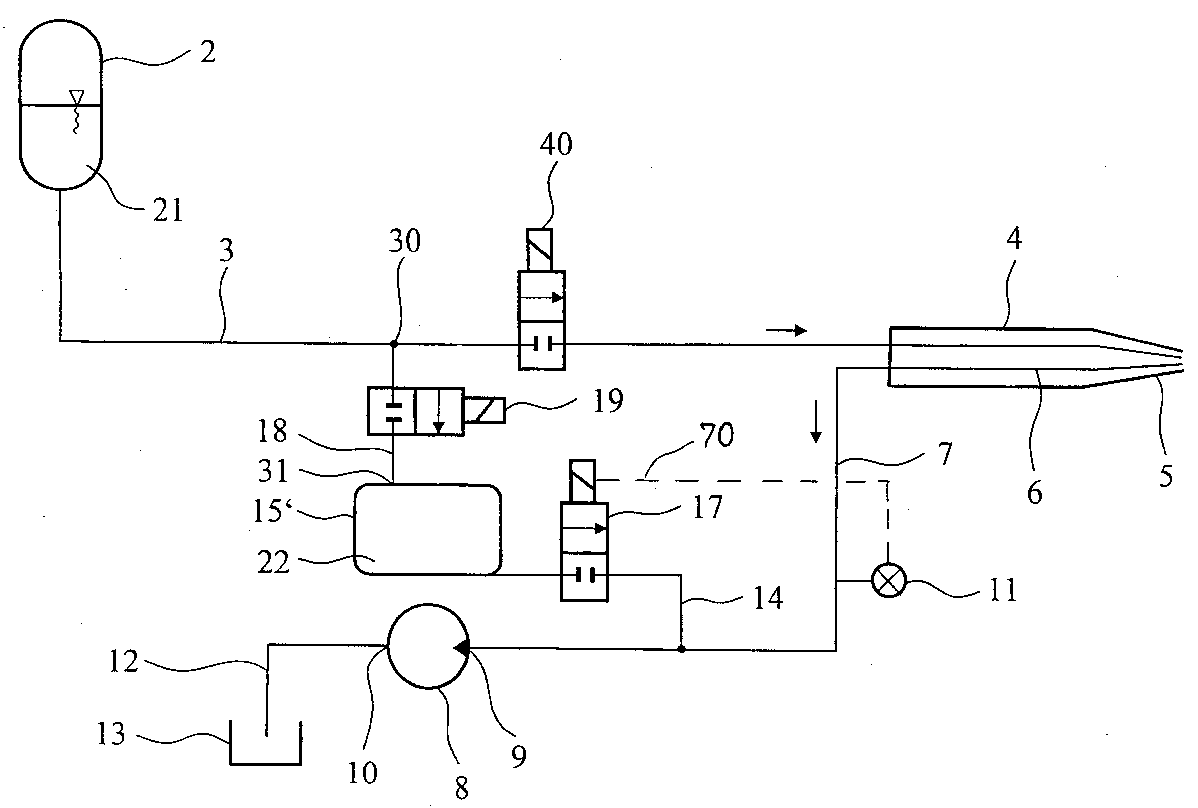
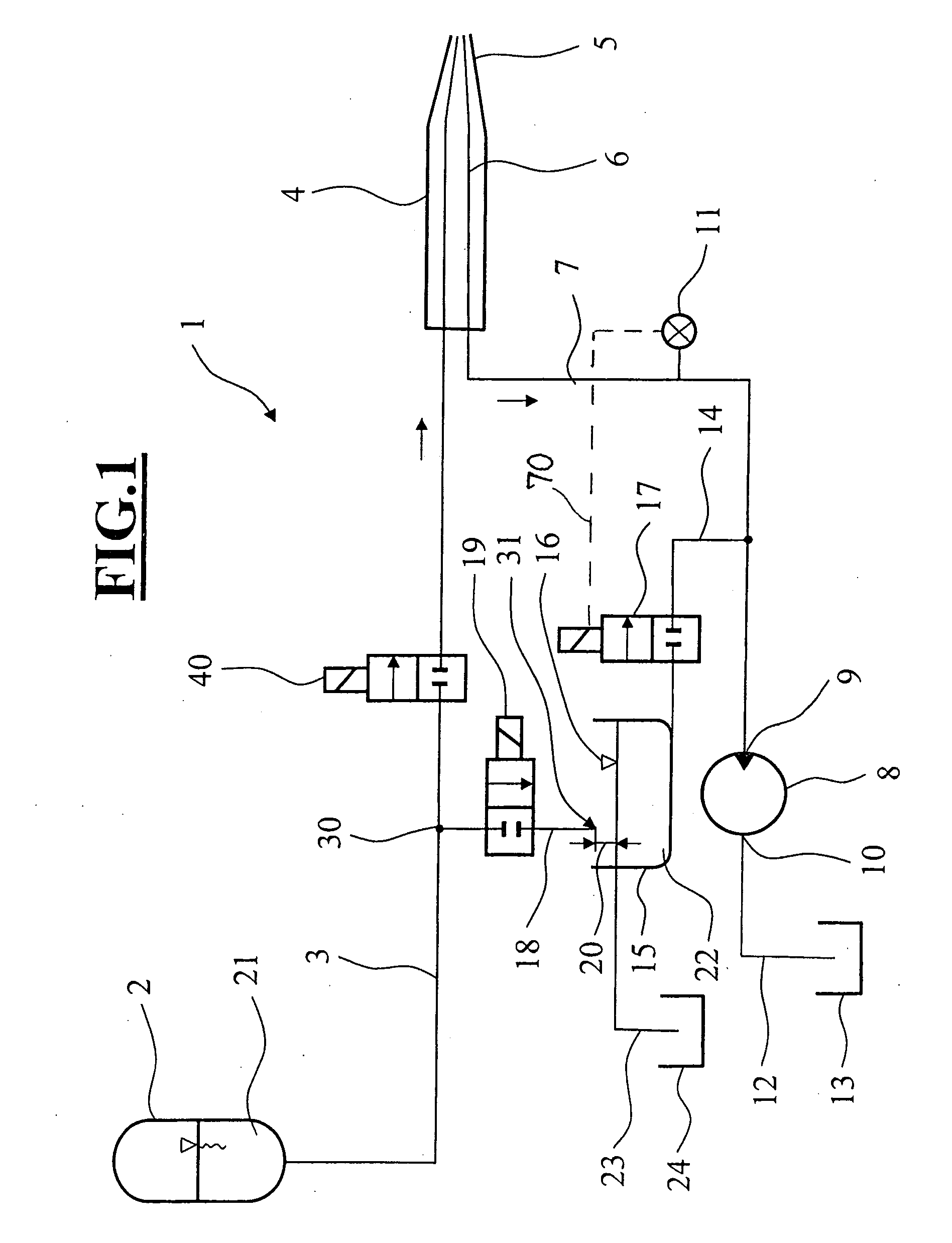
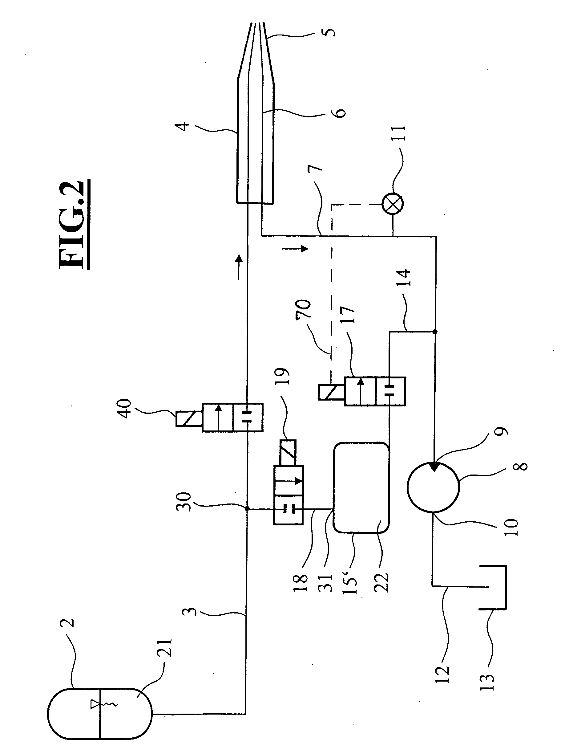
[0025] In FIG. 1, a schematic of an embodiment of the surgical system 1 of the invention is shown. An irrigation fluid 21 is held in a first fluid vessel 2 and this irrigation fluid can be guided via an irrigation line 3 to a surgical handpiece 4. The handpiece 4 can be a handpiece for phacoemulsification wherein a vibrating tip 5 emulsifies a clouded lens of an eye and the broken up lens fragments are drawn away by suction. An irrigation valve 40 is shown in FIG. 1 as a two-way valve and permits a passthrough or blocking of the irrigation fluid in a direction to the handpiece 4. An aspiration line 6 runs from the tip 5 to an end of the handpiece 4 in order to transport away emulsified lens pieces and fluid from the eye. The removal is caused by a suction pump 8 which is connected at its input 9 via an aspiration input line 7 to the handpiece 4. A fluid pressure in the aspiration input line 7 is detected by a pressure sensor 11 which is mounted between the input 9 of the suction pum...


PUM


Abstract

A surgical system controls a fluid and includes an irrigation line for conducting an irrigation fluid; a first fluid vessel for holding the irrigation fluid; and, a surgical handpiece. The irrigation line has a first end connected to the first fluid vessel and a second end connected to the handpiece. The system further includes a suction pump having an inlet and an outlet; an aspiration input line arranged between the inlet of the suction pump and the surgical handpiece so as to permit the suction pump to draw fluid through the surgical handpiece; a pressure sensor for detecting the pressure of the fluid in the aspiration input line; a collection vessel; an aspiration output line connecting the outlet of the suction pump to the collection vessel so as to permit fluid from the outlet of the suction pump to be conducted into the collection vessel; a second fluid vessel for accommodating irrigation fluid therein; an aspiration ventilation line for connecting the second fluid vessel to the aspiration input line; and, a venting valve provided in the aspiration ventilation line and the venting valve being switchable in dependence upon the fluid pressure in the aspiration ventilation line.

Description

CROSS REFERENCE TO RELATED APPLICATIONS [0001] This application claims priority of German patent application nos. 10 2006 042 815.3 and 10 2006 054 628.8, filed Sep. 8, 2006 and Nov. 17, 2006, respectively, the entire contents of which are incorporated herein by reference. FIELD OF THE INVENTION [0002] The invention relates to a surgical system and a method for controlling fluid when treating a cataract with the phacoemulsification technique. BACKGROUND OF THE INVENTION [0003] A clouding of the lens is referred to in medicine as a cataract. Several surgical techniques are available for treating a clouding of the lens. The most widely used technique is phacoemulsification wherein a thin tip is introduced into the sick lens and is excited to vibration with ultrasound. In its immediate vicinity, the vibrating tip emulsifies the lens in such a manner that resulting lens fragments are drawn off by a pump through a line. When the lens has been completely emulsified, then a new artificial ...

Claims


Application Information

Patent Timeline
IPC IPC(8): A61M1/00
CPCA61M1/0058A61M1/0031A61M1/74A61M1/77
Inventor KUBLER, CHRISTOPHEICHLER, MICHAELMAIER, TOBIAS
Owner CARL ZEISS SURGICAL
Why Eureka
Try Eureka