Shock-absorbing cane

Inactive Publication Date: 2008-11-04
ORTIZ RALPH O
View PDF6 Cites 20 Cited by
  • Summary
  • Abstract
  • Description
  • Claims
  • Application Information

AI Technical Summary

Benefits of technology

[0011]According, it is an object of the present invention to provide a shock-absorbing cane that avoids the disadvantages of the prior art.
[0012]Briefly stated, another object of the present invention is to provide a shock absorbing cane, including a shaft and a handle. An additional object of the present invention is to provide a cane, having a shaft that self propels forward and repositions itself, when user lifts compressed handle in a simple and certain manner. Shaft having a controlled forward momentum that moves in unison with every stride or step user takes. The shaft extends from the handle and the handle is shock-absorbing for absorbing impact when the shaft strikes against an unyielding surface. The handle includes a fixed portion, a movable portion, and a dampening assembly. The fixed portion is affixed to the shaft and the movable portion is movably mounted to the fixed portion. The dampening assembly includes a tension spring disposed in the fixed portion of the handle, with one leg thereof extending into the shaft to preload the tension spring by biasing against the shaft, and with the other leg thereof extending via a rod into and affixed to the movable portion of the handle, thereby allowing the movable portion of the handle to resiliently move relative to the shaft and absorb impact when the shaft strikes against the unyielding surface.

Problems solved by technology

Furthermore, even though these innovations may be suitable for the specific individual purposes to which they address, however, they would not be suitable for the purposes of the embodiments of the present invention as heretofore described.

Method used


Image

  • Shock-absorbing cane
  • Shock-absorbing cane
  • Shock-absorbing cane

Examples


Embodiment Construction

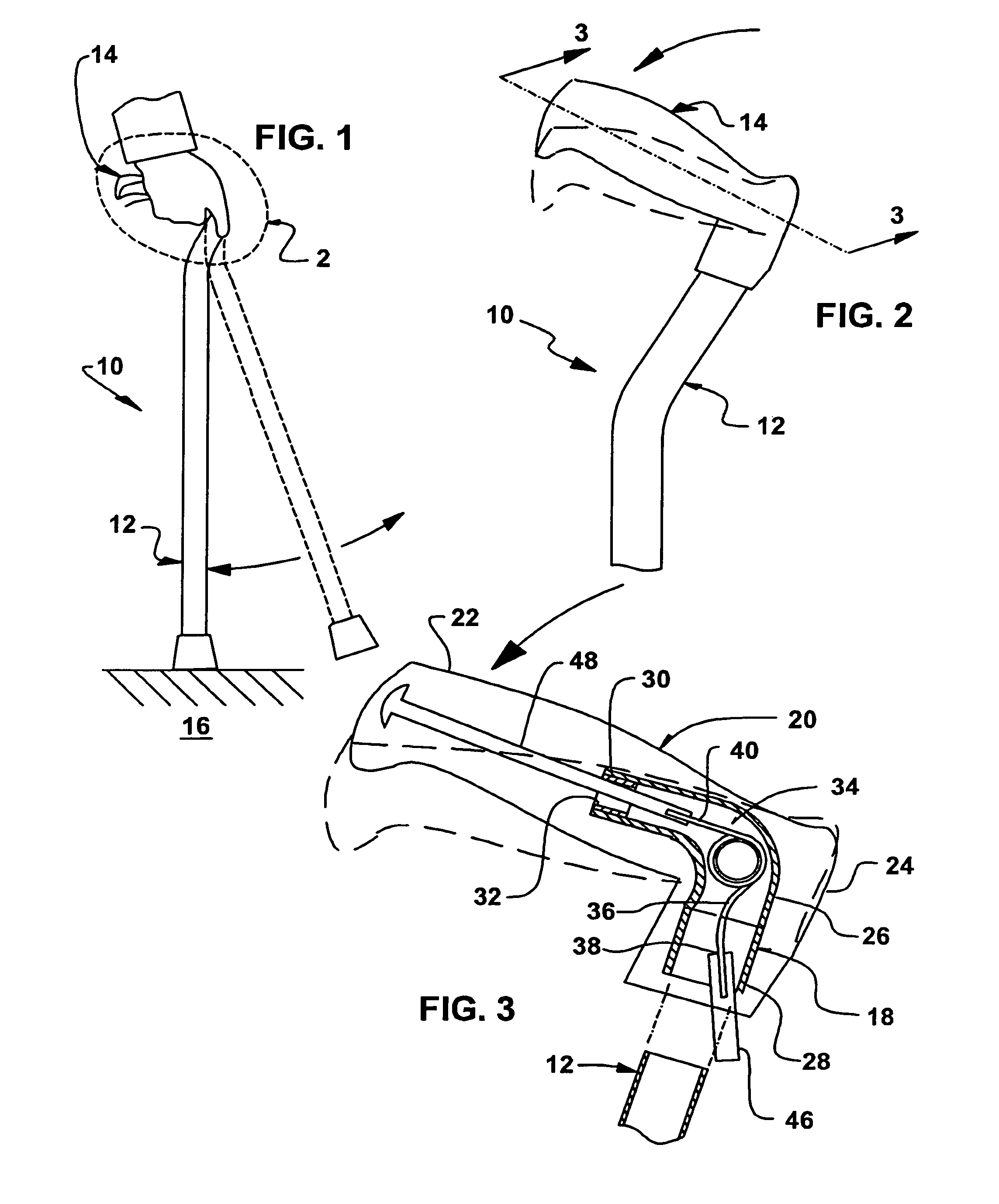
[0041]Referring now to the figures, in which like numerals indicate like parts, and particularly to FIGS. 1 and 2, which are, respectively, a diagrammatic side elevational view of the shock-absorbing cane of the embodiments of the present invention in use, and an enlarged diagrammatic side elevational view of the area generally enclosed by the dotted curve identified by ARROW 2 in FIG. 1 of the shock-absorbing handle of the shock-absorbing cane of the embodiments of the present invention, the shock absorbing cane of the embodiments of the present invention is shown generally at 10.

[0042]The shock-absorbing cane 10 comprises a shaft 12 and a handle 14. The shaft 12 extends from the handle 14. The handle 14 is shock-absorbing for absorbing impact when the shaft 12 strikes against an unyielding surface 16.

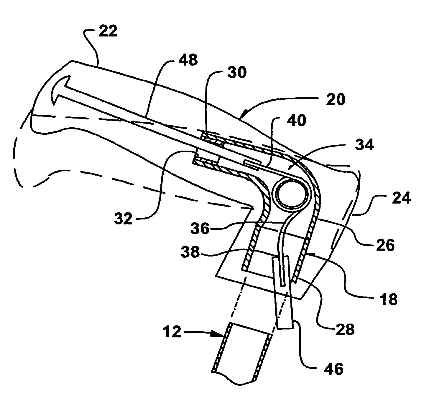
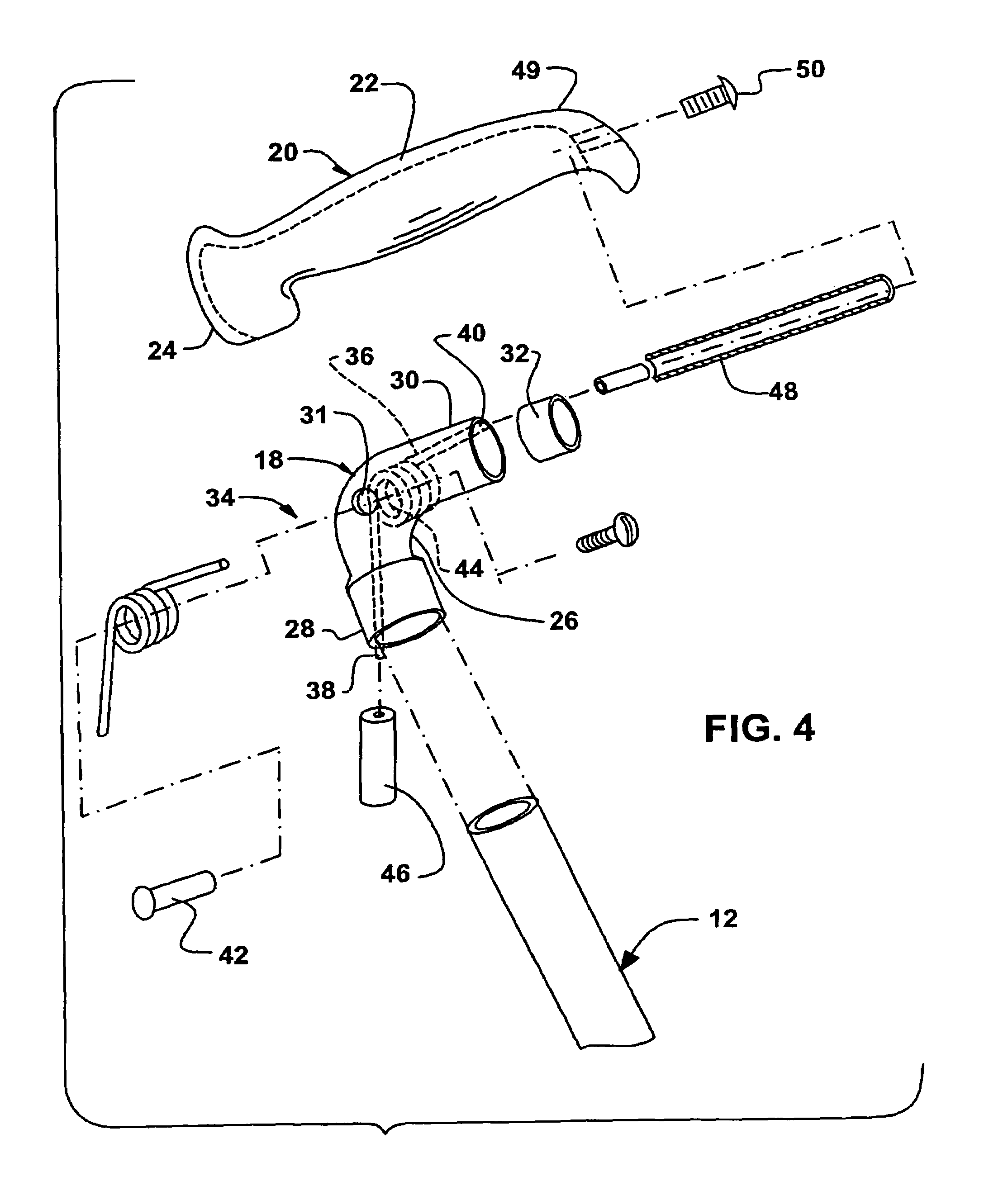
[0043]The configuration of the handle 14 can best can be seen in FIGS. 3 and 4, which are, respectively, an enlarged diagrammatic cross sectional view taken along LINE 3-3 in FIG. 2 o...


PUM


Abstract

A shock absorbing cane, including a shaft and a handle, the shaft having a self propelling and repositioning forward motion when compressed handle is lifted by user. The shaft extends from the handle and the handle is shock-absorbing for absorbing impact when the shaft strikes against an unyielding surface. The handle includes a fixed portion, a movable portion, and a dampening assembly. The fixed portion is affixed to the shaft and the movable portion is movably mounted to the fixed portion. The dampening assembly includes a tension spring disposed in the fixed portion of the handle, with one leg thereof extending into the shaft to preload the tension spring by biasing against the shaft, and with the other leg thereof extending via a rod into and affixed to the movable portion of the handle, thereby allowing the movable portion of the handle to resiliently move relative to the shaft and absorb impact when the shaft strikes against the unyielding surface.

Description

BACKGROUND OF THE INVENTION[0001]1. Field of the Invention[0002]The embodiments of the present invention relates to a cane, and more particularly, the embodiments of the present invention relate to a shock-absorbing cane.[0003]2. Description of the Prior Art[0004]Numerous innovations for canes have been provided in the prior art that will be described. Even though these innovations may be suitable for the specific individual purposes to which they address, however, they differ from the embodiments of the present invention.[0005]A FIRST EXAMPLE, U.S. Pat. No. 2,802,479 published / issued on Aug. 13, 1957 to Hickman teaches a walking cane, including an outer casing support, a handle member, apparatus for slidably mounting a portion of the handle in the upper end of the casing, spring apparatus mounted in the casing adjacent the handle member, a lock bolt secured to the handle portion, longitudinal slot apparatus formed in the casing adapted to slidably receive the lock bolt, an offset s...

Claims


Application Information

Patent Timeline
IPC IPC(8): A45B7/00A45B9/02
CPCA45B9/02A45B7/005A45B9/00
Inventor ORTIZ, RALPH O.
Owner ORTIZ RALPH O
Why Eureka
Try Eureka