
CO2 capture device of internal combustion engine

A capture device and internal combustion engine technology, applied to internal combustion piston engines, exhaust devices, noise reduction devices, etc., can solve the problems of large space occupation, uncompact devices, mixing, etc., and achieve high working capacity and fuel saving effects

Inactive Publication Date: 2015-04-08
北京建筑工程学院
View PDF9 Cites 0 Cited by
  • Summary
  • Abstract
  • Description
  • Claims
  • Application Information

AI Technical Summary

Problems solved by technology

[0004] The utility model patent ZL201020576059.2 gives an idea of ​​the overall process of a liquid oxygen-fixed carbon zero-emission internal combustion engine, but there is no specific design on how to treat CO 2 Fixing; Invention patent application patent CN201010171423.1 has designed an ammonia carbon fixation device, which uses chemical absorption to treat the CO produced by the boiler 2 Fix, but not CO in engine exhaust 2 to capture
Invention patent application publication CN 101639329A designed a car with liquid oxygen and tail gas CO 2 It is a device that conducts partition heat exchange to vaporize liquid oxygen and then passes it into the internal combustion engine to support combustion, but it cannot transfer the vaporized oxygen and the remaining incompletely sublimated CO 2 Mixed, common into the internal combustion engine for combustion
Utility model patent CN 201851229U designed a liquid oxygen vaporized into the internal combustion engine and exhaust CO 2 The fixed recovery device is complex in design, occupies a large space, and the device is not compact. At the same time, the exhaust gas CO 2 Fixed recovery unit with smaller opening

Method used


Image

  • CO2 capture device of internal combustion engine

Examples


Embodiment Construction

[0010] Below in conjunction with accompanying drawing, the present invention is described in further detail:

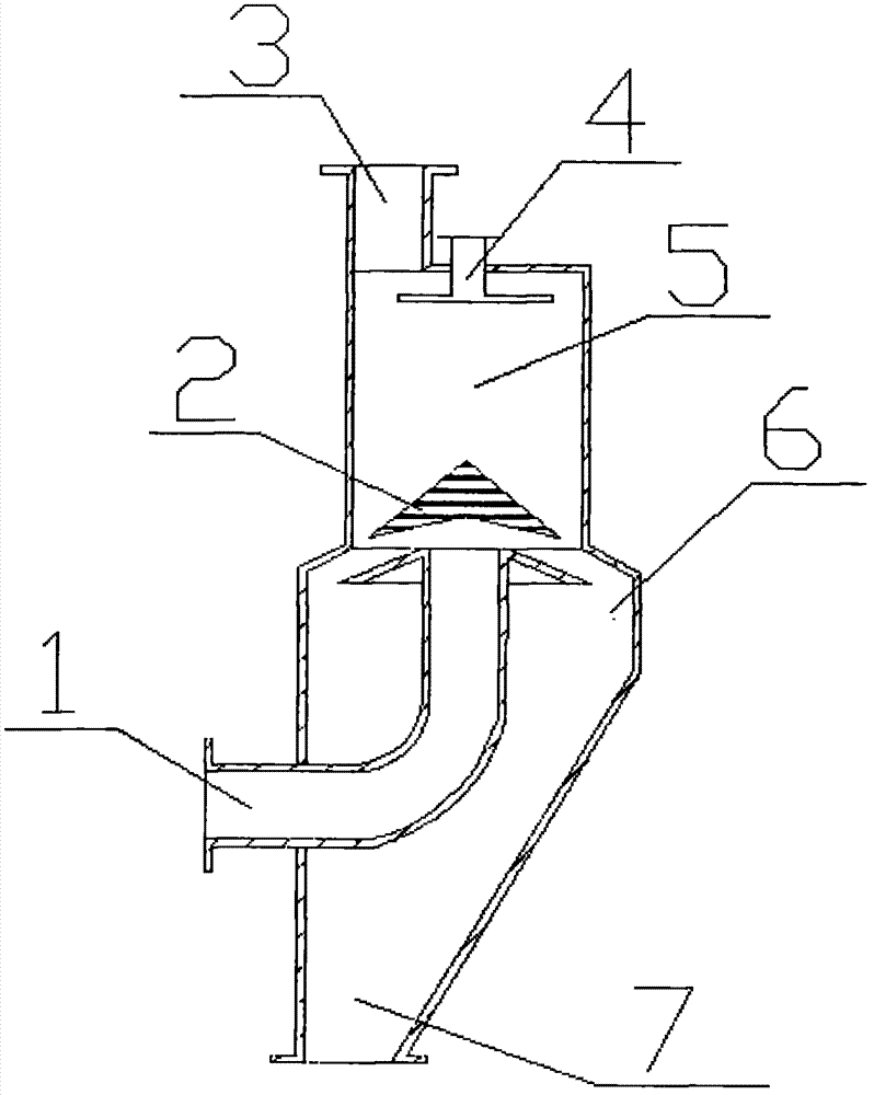
[0011] Concrete technical scheme of the present invention is: as figure 1 , CO 2 The capture device has a casing, the inlet 1 is arranged at the lower part of the casing side, the outlet 3 is arranged at the upper part of the casing, and the dry ice falling block 2 is arranged above the part where the inlet 1 enters the convection heat exchange chamber 5 . CO is further described below 2 Principle of the capture device.

[0012] The tail end of the exhaust pipe of the internal combustion engine is connected to a condensate pipe to condense the exhaust gas to close to 50°C, and the exhaust gas enters the capture device through the inlet 1. Exhaust gas is an internal combustion engine with oxygen and CO 2 Combustion produced by the mixture gas, the main component is CO 2 After entering from the inlet air pipe, it bypasses the bottom of the dry ice descending block ...


PUM


Abstract

The invention discloses a CO2 capture device of an internal combustion engine, which comprises a casing, an inlet (1), a dry ice falling block (2), an outlet (3), a liquid oxygen spray device (4), a convective heat transfer chamber (5), a dry ice falling track (6), and a dry ice collector (7). The internal combustion engine exhaust CO2 is captured, and the liquid oxygen is vaporized to oxygen gas which enters the internal combustion engine together with non-sublimated CO2 to realize oxygen enriched combustion; meanwhile, the generation of NOx and CH and CO is eliminated. The liquid oxygen is introduced into the device and vaporized under heat, the exhaust CO2 releases heat and sublimates to dry ice, and the rest CO2 and vaporized oxygen gas enter the internal combustion engine to carry out oxygen enriched combustion, so that the internal combustion engine realizes zero discharge. The device disclosed by the invention can be used together with the internal combustion engine to enable the internal combustion engine to operate in a narrow space requiring zero discharge, such as military tunnel construction vehicles, tunneling machines, well drilling generators, submarine generators, military missile launching vehicles and other occasions. The dry ice recovered by the device can be reused, and can be sued for refrigeration, dry ice cleaning agents, plant nutrients and the like.

Description

technical field [0001] The invention relates to an internal combustion engine CO 2 Capture device, specifically related to internal combustion engine exhaust CO 2 capture device. Background technique [0002] In today's world, the problem of global warming is the primary problem that plagues the development of many countries. Many countries are looking for new ways to save energy and reduce emissions. In terms of research on carbon sequestration devices, they basically conduct decarbonization research on the tail gas of power plant boilers. There is no device applied to the decarbonization of internal combustion engine tail gas, and this patent will conduct in-depth research on this aspect. It has been confirmed through research that oxy-fuel combustion can support combustion through excess air, so that fuel can be burned more fully, and it is one of the main ways to save energy. Oxygen-enriched combustion can obtain higher pressure peaks and temperature peaks, and can co...

Claims


Application Information

Patent Timeline
Patent Type & Authority Patents(China)
IPC IPC(8): F02M25/07F02M25/10F01N3/02F02M26/00
CPCY02T10/121Y02T10/12
Inventor 刘永峰陈红兵秦建军弋理
Owner 北京建筑工程学院
Learn More