CO2 capture device of internal combustion engine
A capture device and internal combustion engine technology, applied to internal combustion piston engines, exhaust devices, noise reduction devices, etc., can solve the problems of large space occupation, mixing, and uncompact devices, and achieve the effects of fuel saving and high workability
- Summary
- Abstract
- Description
- Claims
- Application Information
AI Technical Summary
Problems solved by technology
Method used
Image
Examples
Embodiment Construction
[0010] Below in conjunction with accompanying drawing, the present invention is described in further detail:
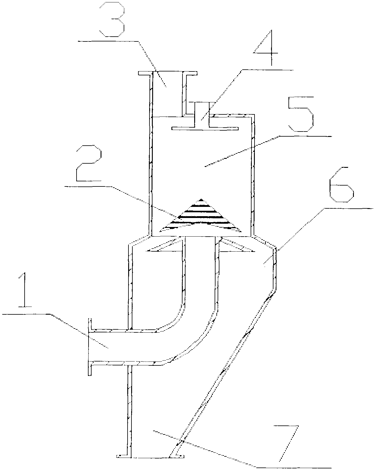
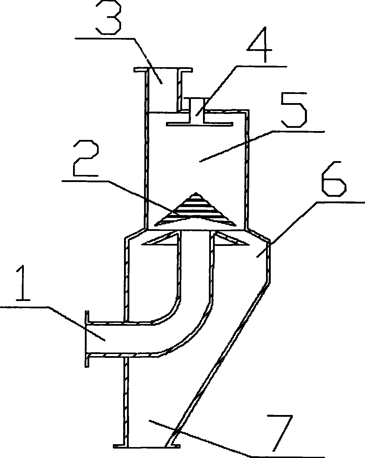
[0011] Concrete technical scheme of the present invention is: as figure 1 , CO 2 The capture device has a casing, the inlet 1 is arranged at the lower part of the casing side, the outlet 3 is arranged at the upper part of the casing, and the dry ice falling block 2 is arranged above the part where the inlet 1 enters the convection heat exchange chamber 5 . CO is further described below 2 Principle of the capture device.
[0012] The tail end of the exhaust pipe of the internal combustion engine is connected to a condensate pipe to condense the exhaust gas to close to 50°C, and the exhaust gas enters the capture device through the inlet 1. Exhaust gas is an internal combustion engine with oxygen and CO 2 Combustion produced by the mixture gas, the main component is CO 2 After entering from the inlet air pipe, it bypasses the bottom of the dry ice descending block ...
PUM
 Abstract
Description
Claims
Application Information
 - R&D
- Intellectual Property
- Life Sciences
- Materials
- Tech Scout
- Unparalleled Data Quality
- Higher Quality Content
- 60% Fewer Hallucinations
Browse by: Latest US Patents, China's latest patents, Technical Efficacy Thesaurus, Application Domain, Technology Topic, Popular Technical Reports.
© 2025 PatSnap. All rights reserved.Legal|Privacy policy|Modern Slavery Act Transparency Statement|Sitemap|About US| Contact US: help@patsnap.com


