Ash removal device for heat exchange pipe of tail flue of boiler

The technology of tail flue and ash cleaning device is applied in the field of ash cleaning device for heat exchange tube of boiler tail flue, which can solve the problems of high energy consumption, economic loss of power plants and factories, long operation period, etc. The effect of low investment cost and short cleaning cycle

Inactive Publication Date: 2012-08-22
SOUTHEAST UNIV
View PDF5 Cites 1 Cited by
  • Summary
  • Abstract
  • Description
  • Claims
  • Application Information

AI Technical Summary

Problems solved by technology

Although the effects of these methods are obvious, the equipment investment and operating costs are high, and they are not suitable for small boiler equipment. Moreover, these soot blowing methods have troubles such as shutdown and cleaning, and long operating cycles, which cause huge economic losses to power plants and factories; The method of mechanical vibration (beating) makes the heating surface vibrate, and the ash deposits are separated from the wall and taken away by the flue gas. The method is simple and can be cleaned without stopping the furnace, but it consumes a lot of energy and is not efficient, and the equipment is heavy.

Method used


Image

  • Ash removal device for heat exchange pipe of tail flue of boiler
  • Ash removal device for heat exchange pipe of tail flue of boiler
  • Ash removal device for heat exchange pipe of tail flue of boiler

Examples


Embodiment Construction

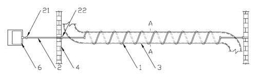
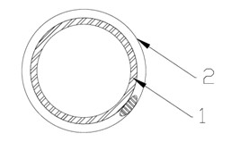
[0025] The boiler tail flue heat exchange tube soot cleaning device of the present invention comprises a coil spring 1 and a pull rod 2, the axial direction of the pull rod 2 is parallel to the stretching direction of the coil spring 1, one end of the pull rod 2 is connected with one end of the coil spring 1, and the coil spring 1 is wound on the outside of the cleaned heat exchange tube 3, and the tie rod 2 passes through the flue wall 4 of the boiler where it is located. A second blocking and sealing plate 22 is provided on the rod section inside the wall 4 .

[0026] In an embodiment of the present invention, there is one pull rod 2 , and the end of the coil spring 1 not connected to the pull rod 2 is fixed inside the flue wall 4 .

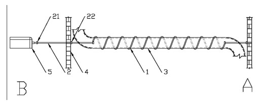
[0027] In another embodiment of the present invention, the two ends of the coil spring 1 are respectively connected with a pull rod 2, and the dust cleaning operation process is carried out at both ends in sequence during operation, and the spe...


PUM


Abstract

The invention relates to an ash removal device for a heat exchange pipe of a tail flue of a boiler, which comprises a helical spring and a pull rod. The axial direction of the pull rod is parallel to the extension and retraction direction of the helical spring; one end of the pull rod is connected with one end of the helical spring; the helical spring is wound outside the cleaned heat exchange pipe; the pull rod passes through the flue wall of the boiler; a first stop sealing plate is arranged on a rod section of the pull rod, which is positioned outside the flue wall; and a second stop sealing plate is arranged on a rod section of the pull rod, which is positioned inside the flue wall. According to the device disclosed by the invention, the accumulated dust attached onto the outer surface of the heat exchange pipe is removed by utilizing the relative motion of the helical spring along the axial direction of the outer wall of the heat exchange pipe, which is generated by the retracting and extending motion of the helical spring wound on the outer wall of the heat exchange pipe.

Description

technical field [0001] The invention belongs to the field of industrial applications, and in particular relates to a device for removing dust from boiler tail flue heat exchange tubes and a using method based on the device. Background technique [0002] In coal-fired boilers, heat exchangers such as economizers and air preheaters are arranged in the tail flue. When the ash-laden flue gas passes through each heating surface, some ash particles will be deposited on the heating surface to form ash. Timely and effective cleaning will eventually lead to an increase in boiler exhaust gas temperature, a decrease in thermal efficiency, corrosion of the heating surface, and an impact on the economy and safety of boiler equipment. Especially in garbage incinerators, the corrosion phenomenon of the heating surface at the tail is more serious after dust accumulation. How to effectively deal with the ash deposits in the heat exchange tubes in the tail flue is very important to the stabl...

Claims


Application Information

Patent Timeline
Patent Type & Authority Applications(China)
IPC IPC(8): F23J3/02
Inventor 吴新王军龙赵长遂陈晓平
Owner SOUTHEAST UNIV
Why Eureka
Try Eureka