Fixture used for band saw machine tool

A technology of machine tools and band saws, which is applied in the field of fixing devices, can solve problems such as the inability to fix thinner workpieces to be sawed, and achieve the effects of easy adjustment, simple structure, and improved reliability

Inactive Publication Date: 2012-08-22
YANGZHOU RONGDE NEW ENERGY TECH +1
View PDF7 Cites 1 Cited by
  • Summary
  • Abstract
  • Description
  • Claims
  • Application Information

AI Technical Summary

Problems solved by technology

[0004] The technical problem to be solved by the present invention is to overcome the disadvantage that the existing fixing fixture of the band saw itself cannot fix the thinner workpiece to be sawed, and provide a clamp for the band saw machine tool that can reliably fix the thinner workpiece to be sawed

Method used


Image

  • Fixture used for band saw machine tool
  • Fixture used for band saw machine tool
  • Fixture used for band saw machine tool

Examples


Embodiment Construction

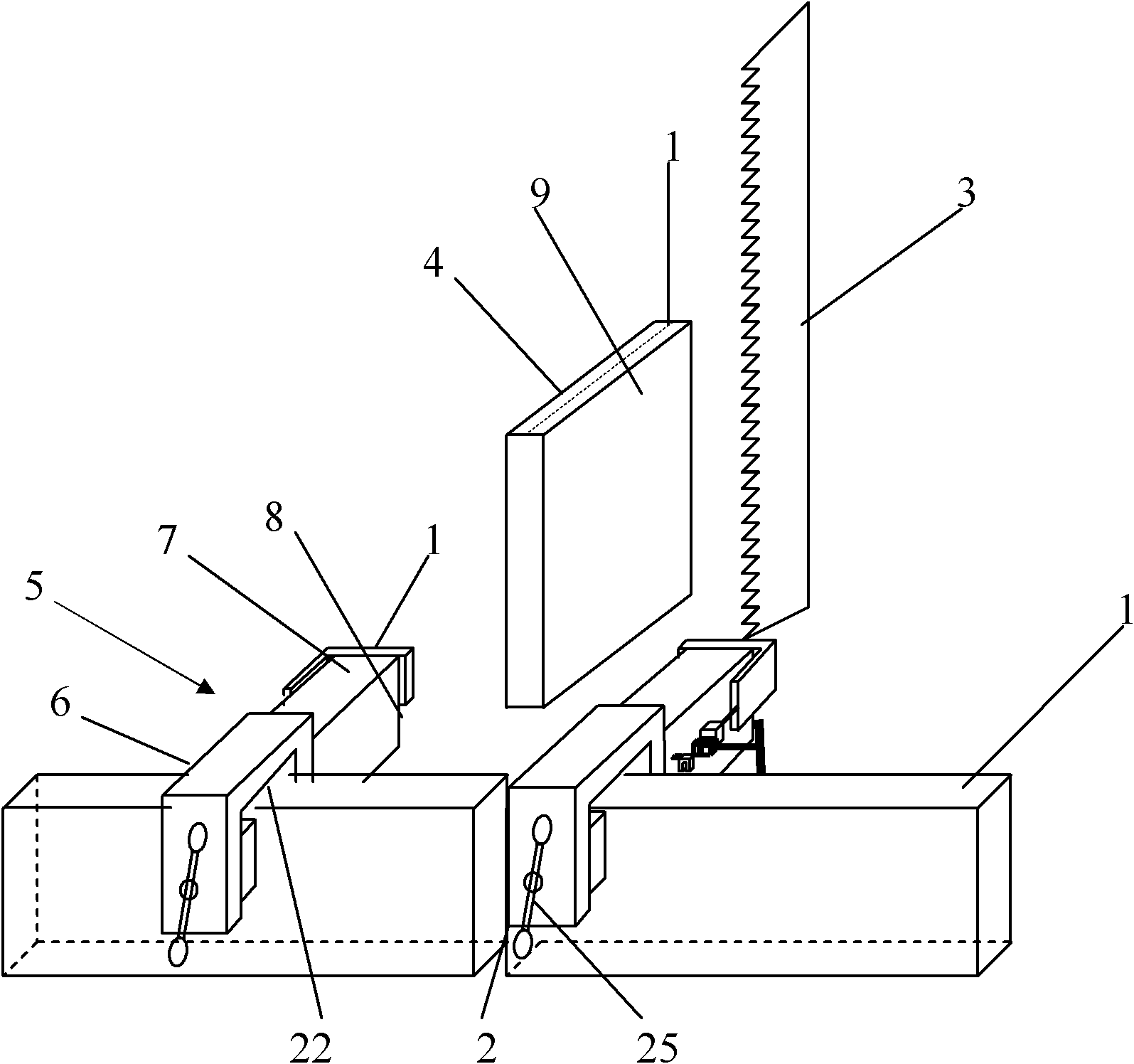
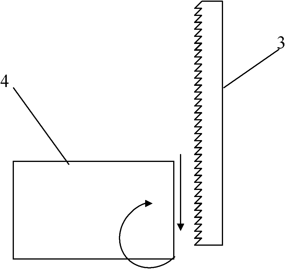
[0030] figure 1 It is a structural schematic diagram of an embodiment of the clamp for band saw machine tool of the present invention, as figure 1 As shown, the fixture of the band saw machine tool of the present invention, the band saw machine tool has a horizontal workbench for placing workpieces to be sawed, one side of the horizontal workbench is vertically provided with a clamping table 1, and the horizontal workbench And the clamping platform 1 is provided with a saw blade passing slot 2 perpendicular to the clamping platform 1 . In the working state, the saw blade 3 moves vertically, and as the horizontal workbench is fed horizontally, the workpiece 4 to be sawed is cut into two parts by the saw blade 3 . The clamp includes two clamping parts 5 arranged in parallel on the clamping table 1 , and the two clamping parts 5 are respectively fixed on the clamping table 1 on both sides of the saw blade passing slot 2 . In this embodiment, the structures of the two clamping p...


PUM


Abstract

The invention relates to a fixture used for a band saw machine tool. The band saw machine tool is provided with a horizontal workbench which is used for placing a workpiece to be sawed, wherein one side of the horizontal workbench is vertically provided with a clamping platform, and the horizontal workbench and the clamping platform are provided with a saw blade penetrating seam which is perpendicular to the clamping platform. The fixture comprises two clamping elements, wherein each clamping element comprises a clamp part and a clamping part, the clamp part is detachably fixed on the clamping platform, the clamping part is connected to the clamp part, provided with a clamping surface parallel to the penetrating seam, and used for clamping the workpiece to be sawed, the two clamping elements are respectively fixed on the clamping platform on two sides of the penetrating seam, and two clamping surfaces opposite to the two clamping elements are used for clamping the workpiece to be sawed. The fixture used for the band saw machine tool can be used for overcoming the defect that a fixed fixture of the existing band saw cannot be used for fixing a thinner workpiece to be sawed, and reliably fixing the thinner workpiece to be sawed.

Description

technical field [0001] The invention relates to a fixing device, in particular to a clamp for a band saw machine tool. Background technique [0002] In the process of cutting polysilicon ingots into polysilicon wafers, the head material with a high impurity content and a thickness of about 30mm is usually removed, and the head material will be put into the polysilicon furnace to form polysilicon ingots with other polysilicon raw materials. The head material generally includes a waste layer with a thickness of about 8mm to 10mm. Before putting the head material into the polysilicon furnace, the waste layer must be removed from the head material to ensure the quality of the cast polysilicon ingot and the polysilicon processed from it. The efficiency of the battery. At present, the waste layer is generally processed by manual grinding, that is, the waste layer is ground away by using abrasive tools (such as bowl-shaped pieces). [0003] On the one hand, this method cannot com...

Claims


Application Information

Patent Timeline
IPC IPC(8): B23D55/04
Inventor 鄢康王学铭惠昌军
Owner YANGZHOU RONGDE NEW ENERGY TECH
Why Eureka
Try Eureka