
LED circuit board and manufacturing method thereof

A LED circuit board, circuit board technology, applied in the direction of printed circuit, printed circuit manufacturing, printed circuit components, etc., can solve the problems of LED circuit board cost increase, high energy consumption, environmental pollution, etc., to improve reliability and practicality The effect of working life, simplifying the manufacturing process and product structure, reducing environmental pollution and energy consumption

Inactive Publication Date: 2012-08-08
田茂福
View PDF7 Cites 5 Cited by
  • Summary
  • Abstract
  • Description
  • Claims
  • Application Information

AI Technical Summary

Problems solved by technology

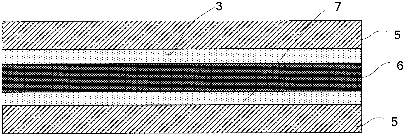
[0004] For example, the copper foil layers 3, 7 need to be bonded to the insulating layer 6 by, for example, an adhesive process, and sometimes an additional adhesive layer needs to be laid, and the complexity of the process steps and the additional adhesive material will cause the finished product of the LED circuit board to be damaged. Increased costs;
[0005] The circuit structure of copper foil layers 3 and 7 will be realized by etching, and the interlayer conduction of copper foil layers 3 and 7 needs to be achieved by plating through holes, so it will inevitably pollute the environment, and it can consumption is also high;
[0006] Copper foil layer 3, 7 and insulating layer 6, cover film layer 5, 5 will inevitably affect the wiring board and / or insulating layer and / or the process steps of opening windows in the cover film layer, which further increases the complexity of its manufacturing process, and may affect the final reliability of the product due to its alignment process, which in turn affects the product yield and actual working life

Method used


Image

  • LED circuit board and manufacturing method thereof
  • LED circuit board and manufacturing method thereof
  • LED circuit board and manufacturing method thereof

Examples


Embodiment Construction

[0026] The present invention will be described in more detail below by taking a double-sided flexible printed circuit board suitable for mounting LEDs and other components as a specific embodiment. However, it should be understood that the present invention is not only applicable to double-sided flexible printed circuit boards, but also to double-sided rigid printed circuit boards (also known as "hard boards" in the industry), and multi-layer LED circuits with more than two circuit layers. plate.

[0027] In addition, the term "double-sided flexible printed wiring board" means that wiring is provided on both sides of the flexible printed wiring board.

[0028] Before describing the present invention in detail, those skilled in the art should understand that "component" should be understood in the broadest sense in this application, that is, it includes all types of electronic components, electrical components or other types of components used in circuits, For example, various...


PUM


Abstract

The invention relates to an LED circuit board and a manufacturing method thereof. More particularly, provided in the invnetion is an LED circuit board, comprising: a circuit layer (8), which is directly formed by a single-layer metal material; and cover layers (5,5), which are respectively covered on the right side and the back side of the circuit layer. Besides, provided is a method for manufacturing the LED circuit board. The method comprises the following steps: providing a single-layer metal material; carrying out first-time punching or cutting on the single-layer metal material so as to form the circuit layer (8); attaching the back-side cover film (5) on the back side of the circuit layer (8) and carrying out stitching; carrying out punching or cutting on the circuit layer (8) for the second time to form a nascent circuit board (8); and attaching the right-side cover film (5) on the right side of the nascent circuit board (8) and carrying out stitching. According to the invention, a structure including a PI layer clamped between two layers of coppers in a current LED circuit board product is directly eliminated and a copper foil layer is used for replacement, thereby simplifying the manufacturing technology and the product structure, reducing cost, environmental pollution and energy consumption, improving reliability of the product and prolonging actual working life.

Description

technical field [0001] The invention relates to the field of printed circuit boards, in particular to a novel LED circuit board and a manufacturing method thereof. Background technique [0002] In the LED circuit board of the prior art, such as figure 1 As shown, the structure of the LED circuit board is that the middle is an insulating layer 6 (for example, made of a typical PI material), and the two sides of the insulating layer are respectively provided with (for example, by bonding) circuit layers 3, 7 (for example, a typical copper foil), on the outside of the two layers of circuit layers are respectively provided (for example, by bonding, coating, coating or printing) protective cover film layers 5, 5 (typically CVL). [0003] The defects of this prior art LED circuit board are various. [0004] For example, the copper foil layers 3, 7 need to be bonded to the insulating layer 6 by, for example, an adhesive process, and sometimes an additional adhesive layer needs t...

Claims


Application Information

Patent Timeline
Patent Type & Authority Applications(China)
IPC IPC(8): H05K1/02H05K3/00H05K3/10
Inventor 田茂福
Owner 田茂福
Learn More