
Optical signal and relay method, apparatus, system and application of luminous energy transmission

A relay device, optical signal technology, applied in transmission systems, electromagnetic wave transmission systems, optical fiber transmission, etc., can solve the problems of not including repeater effect, not including effect, not including repeater, etc.

Active Publication Date: 2012-08-01
CHERRY TREE CONSULTING
View PDF16 Cites 26 Cited by
  • Summary
  • Abstract
  • Description
  • Claims
  • Application Information

AI Technical Summary

Problems solved by technology

[0005] In 2007, Nakagawa Laboratories, Inc. of Japan passed the EU patent EP1855398A1, the patent name "Illumination light communication device", disclosed a communication link using multiple white LEDs as light sources for optical communication, but did not include the related repeater of the present invention Effect
[0006] In 2009, Nakagawa Laboratories, Inc. of Japan passed the U.S. patent US patent 7583901, the patent name "Illumination light communication device", disclosed that the power line is used to transmit signals to multiple white LED light sources, as broadcasting (broadcasting) signals, airspace multi-tasking type Communication system technology, but does not include the effect of the related repeater of the present invention
[0007] In 2010, Ian Ashdown disclosed in the US patent US patent 7689130, the patent name "Method and apparatus for illumination and communication", the technology of using PWM and PCM to modulate lighting LEDs to realize optical communication, but did not include the related relay of the present invention device effect
[0008] In 2008, Lai Lihong, Huang Fang, Xie Wensheng, Lai Liwen and others disclosed a method of using area selection growth in Taiwan Patent TW200828634, the title of the invention is "Single-chip optical chip including solar modules and light-emitting modules and its manufacturing method". The method produced includes the integration of solar cells and light-emitting components into a single-chip semiconductor process, which shows the feasibility of combining solar cells and LEDs as solar illuminator in a single-chip process, which can be used in the field of lighting, but does not include the relevant relay of the present invention. device effect
[0012] In 2009, Lubin Zeng, D.O'Brien, Hao Minh, G.Faulkner, Kyungwoo Lee, Daekwang Jung, YunJe Oh, Eun Tae Won, et al. published in IEEE Journal on Selected Areas in Communications, vol.27, no. 9. In the paper "High Data rate multiple input multiple output (MIMO) optical wireless communications using white led lighting" of pp.1654-1662, it is disclosed that the visible light LED array is used as the optical signal source, and the multi-point sensor is used as the optical signal detection component. Experiments confirm the feasibility of the array type optical transceiver communication in conjunction with MIMO communication technology, but do not include the effect of the relevant repeater of the present invention
[0013] In 2006, June-Hun Kim, Chung Ghiu Lee, Chul Soo Park, Swook Hann, Dong-Hwan Kim and other Korean scholars published "Visible light communication at 20Mb / s using illumination LEDs" in Proc.of SPIE 6353, 635340. This paper reveals Research on the feasibility of signal transmission by combining red LEDs with multi-color wavelengths of blue LEDs as a communication optical signal source, but does not include the effect of the related repeater of the present invention
[0015] In 2003, Komine et al published a paper "Integrated system of white LED visible-light communication and power-line communication" in IEEE Trans.On consumer electronics 49(1):71-79, revealing that power-line modem is used as network communication The source of the electrical signal is to use the visible light LED array as the optical signal light source. Experiments have confirmed the feasibility of communicating with the white light visible light LED array as the light signal light source, but the effect of the related repeater of the present invention is not included.
[0016] In 2010, Korean Samsung Electronics company Yoo Jeong Hyun et al. disclosed in the US patent 7663501 patent "Apparatus and method of controlling emitting color of visible light according to a current communication state in a VLC device" that in the visible light communication system, the light source color control device is similar to Wavelength division multiplexing (wavelength division multiplexing) technology in optical fiber communication, but does not include the effect of the relevant repeater of the present invention
[0017] In 2009, Avago Technologies ECBU IP (Singapore) Pte.Ltd. company Gim Eng Chew and others disclosed "Gain control system for visible light communication systems" in US patent US patent 7601940. This patent discloses that the light detector is connected with an adjustable gain amplifier , a gain controller so that the light receiving signal gain in the visible light point-to-point communication system can be controlled, but does not include the effect of the relevant repeater of the present invention
[0018] In 2008, Zhan Xianwu of Ningbo Andy Optoelectronics Technology Co., Ltd. disclosed "white light emitting diode" in the patent CN101140973 of the People's Republic of China. This patent discloses the composition and manufacturing method of white light emitting diodes, but does not include the related repeater effect of the present invention
[0019] In 2006, Toka Tanabe, Hiroshi Yamamoto, and Norihisa Tan of Schibat Products Chemical Co., Ltd. disclosed "novel organic light-emitting components" in Taiwan patent TW200602462. This patent discloses organic light-emitting materials that can be used as soft white lighting optoelectronic materials, but does not include the relevant repeater effect of the present invention
[0020] In 2010, BRUCE BRYAN disclosed "bioluminescent novel objects" in Taiwan patent TW I319472. This patent discloses systems and devices for producing bioluminescence, and the combination of these systems and devices with inanimate products to produce novel objects, but The effect of the present invention is not included

Method used


Image

  • Optical signal and relay method, apparatus, system and application of luminous energy transmission
  • Optical signal and relay method, apparatus, system and application of luminous energy transmission
  • Optical signal and relay method, apparatus, system and application of luminous energy transmission

Examples


Embodiment Construction

[0037] The present invention itself and its preferred mode of combination of devices, further exhibiting the advantages of application to systems extending distances and providing self-sufficient energy sources, will be best understood by reference to the following description of illustrative embodiments read in conjunction with the accompanying drawings, However, the preferred embodiment is only for illustration rather than limiting the present invention.

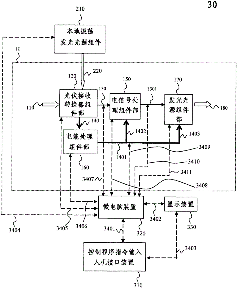
[0038] Such as figure 1 As shown, the optical signal input and optical energy input 110 include input optical communication signals and input optical energy. The optical signal input adopts 5 white light-emitting diodes, which are digitally modulated by OOK (ON-OFF Keying), so that the white light signal becomes an input optical communication signal 110 that flickers brightly and darkly. Light energy is input to part 110, and the energy of the DC signal part of the light signal light is directly used. In this embodiment,...


PUM


Abstract

The present invention provides an optical signal and a relay method, apparatus, system and application of luminous energy transmission, relating to a wireless optical communication signal and a connection relay method, apparatus, mechanism, system, network and Internet of wireless luminous energy transmission. In one embodiment, inputted optical signal and luminous energy irradiate a photovoltaic receiving converter assembly portion, and an electrical signal and electrical energy are generated; through an electric signal processing assembly portion and an electrical energy assembly portion, a reproduced electric signal and electrical energy are recovered and then are sent to a luminescent light source assembly portion through an electrical signal bus circuit to be converted into an optical signal and luminous energy output, and functions of a relay signal and relay energy can be reached at the same time. In other embodiments, a local oscillator light source assembly, an electrical signal access device and a programmable device are added respectively. A mechanism embodiment explains that the relay apparatus of the invention can convert a space layout method and system of a communication link. According to the invention, functions of utilizing a repeater to relay bridging between various networks and providing the Internet are revealed.

Description

technical field [0001] The field of the invention belongs to the technical field of integration of communication and energy fields. The present invention relates to a connection and relay method, device, mechanism, system, network and Internet for wireless optical communication signal and wireless optical energy transmission, and especially relates to the simultaneous use of self-supplied energy and solar energy for communication signals and dual energy sources Energy relay. This system can also be simply applied to a relay system for optical energy transmission. Background technique [0002] In 1970, US patent 3900404 "optical communication system" disclosed the technology of using fluorescent lamp light, or fluorescent lamp, as a communication light source, but did not include the effect of the related repeater of the present invention. If the optical communication system in the future needs to extend the distance of the communication signal and needs to use a repeater, ...

Claims


Application Information

Patent Timeline
Patent Type & Authority Applications(China)
IPC IPC(8): H04B10/10H04B10/17H04B10/2575H04B10/29
Inventor 曹士林
Owner CHERRY TREE CONSULTING
Learn More