Oscillation circuit having shield wire, and electronic apparatus

A technology of oscillating circuits and terminals, applied in the direction of power oscillators, electrical components, etc.

Inactive Publication Date: 2012-08-01
SEIKO INSTR INC
View PDF1 Cites 2 Cited by
  • Summary
  • Abstract
  • Description
  • Claims
  • Application Information

AI Technical Summary

Problems solved by technology

However, a method for stably realizing such a small load capacitance, and a specific method for mounting an oscillation circuit on a mounting board in order to reduce the stray capacitance Cs, have not yet been established.

Method used


Image

  • Oscillation circuit having shield wire, and electronic apparatus
  • Oscillation circuit having shield wire, and electronic apparatus
  • Oscillation circuit having shield wire, and electronic apparatus

Examples


Embodiment Construction

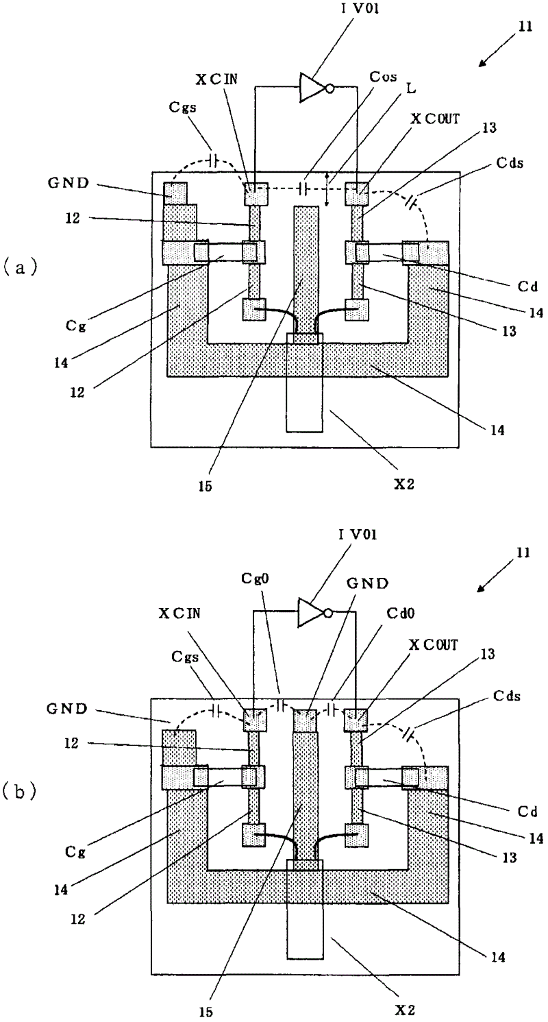
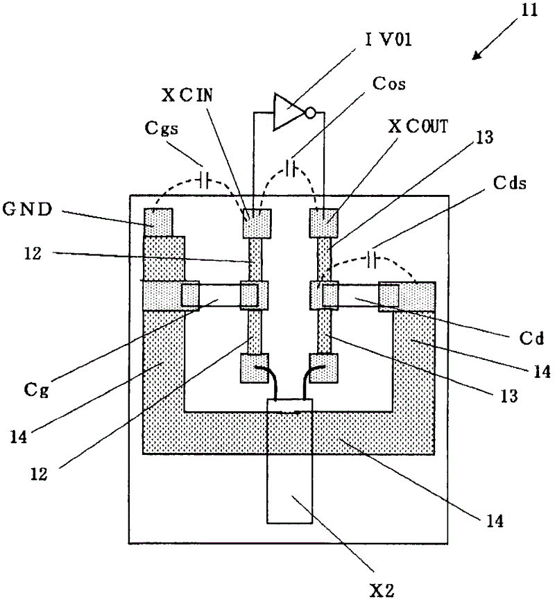
[0036] An object of the present invention is to provide a means for reducing stray capacitance CS in a crystal oscillation circuit disposed on a mounting substrate, thereby reducing load capacitance CL in the crystal oscillation circuit. Specifically, the stray capacitance Cs also significantly changes with the routing of the signal and power wiring, and the inventors have found through various experiments that it can be significantly reduced by taking the ground (ground), that is, the ground potential (Vss) line. Here, the crystal oscillator circuit refers to an oscillator circuit using a crystal vibrator as a piezoelectric vibrator.

[0037] figure 2 It is a layout diagram schematically showing a conventional oscillation circuit on which a crystal oscillator X2 and a mounting board of two external capacitive elements (Cg, Cd) are arranged, and stray capacitance generated in the circuit is shown by a dotted line. On the mounting substrate 11, an external capacitance element...


PUM


Abstract

There is provided an oscillation circuit including a crystal vibrator that is connected between input and output terminals of a CMOS inverter making up the oscillation circuit; an input wiring line that includes a crystal vibrator-side input terminal connected to an input terminal pad of the CMOS inverter; an output wiring line that includes a crystal vibrator-side output terminal connected to an output terminal pad of the CMOS inverter; a ground power source wiring line that includes a crystal vibrator-side ground power source terminal; and a capacitative element that is connected between the input wiring line and the ground power source wiring line, and between the output wiring line and the ground power source wiring line, wherein the ground power source wiring line is disposed at least a part of between the input wiring line and the output wiring line.

Description

technical field [0001] The present invention relates to a method for realizing a low-power-consumption quartz (crystal) oscillation circuit, and in particular to a method for reducing the load capacitance constituting the quartz oscillation circuit. Background technique [0002] In portable devices such as clocks, mobile phones, etc., since the device is required to operate for a long time in a non-charging state or the frequency of charging the mounted battery is required to be reduced, it is increasingly necessary to reduce the frequency of the quartz oscillator used in the device. The driving power of the oscillation circuit of the piezoelectric element and ultra-low power consumption during the standby state of the oscillation circuit (in the state where the oscillation circuit oscillates and when there is no load) are achieved. [0003] Figure 12 A typical oscillation circuit using a quartz vibrator as a piezoelectric vibrator includes: a CMOS inverter IV01 that become...

Claims


Application Information

Patent Timeline
Patent Type & Authority Applications(China)
IPC IPC(8): H03B5/32
CPCH03B5/364
Inventor 相马弘之
Owner SEIKO INSTR INC
Why Eureka
Try Eureka