Light source device and projector
A light source device and light source technology, applied in the direction of light source, electric light source, projection device, etc., can solve the problems such as the reduction of beam light utilization efficiency
- Summary
- Abstract
- Description
- Claims
- Application Information
AI Technical Summary
Problems solved by technology
Method used
Image


Examples
Embodiment 1
[0128] Next, Embodiment 1 of the present invention will be described with reference to the drawings.
[0129] The structure of the projector.
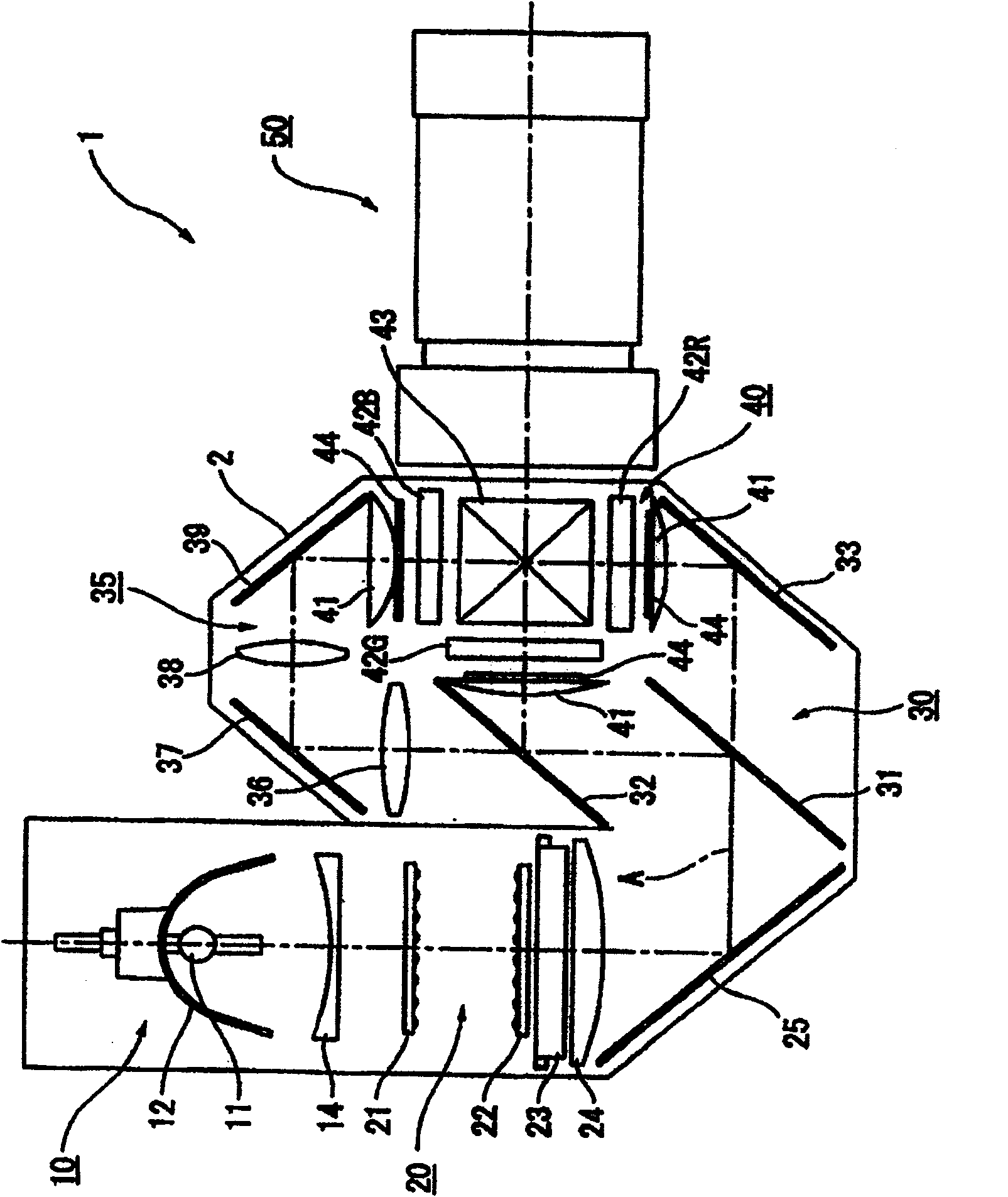
[0130] figure 1 It is a schematic diagram showing the optical system of the projector 1 of the first embodiment.
[0131] The projector 1 is an optical device that modulates a light beam emitted from a light source according to image information to form an optical image, and enlarges and projects it on a screen.
[0132] Such as figure 1 As shown, the projector 1 is configured to include a light source device 10, a uniform illumination optical system 20, a color separation optical system 30, a relay optical system 35, an optical device 40, and a projection optical system 50 as a projection optical device. The optical elements of the optical systems 20 to 35 and the optical device 40 are positioned and accommodated in the housing 2 for optical components in which a predetermined illumination optical axis A is set.
[0133] The light...
Embodiment 2
[0250] Next, Embodiment 2 of the present invention will be described with reference to the drawings.
[0251] In the following description, the same structure and the same components as those of the above-mentioned first embodiment are given the same reference numerals, and their detailed descriptions are omitted or simplified.
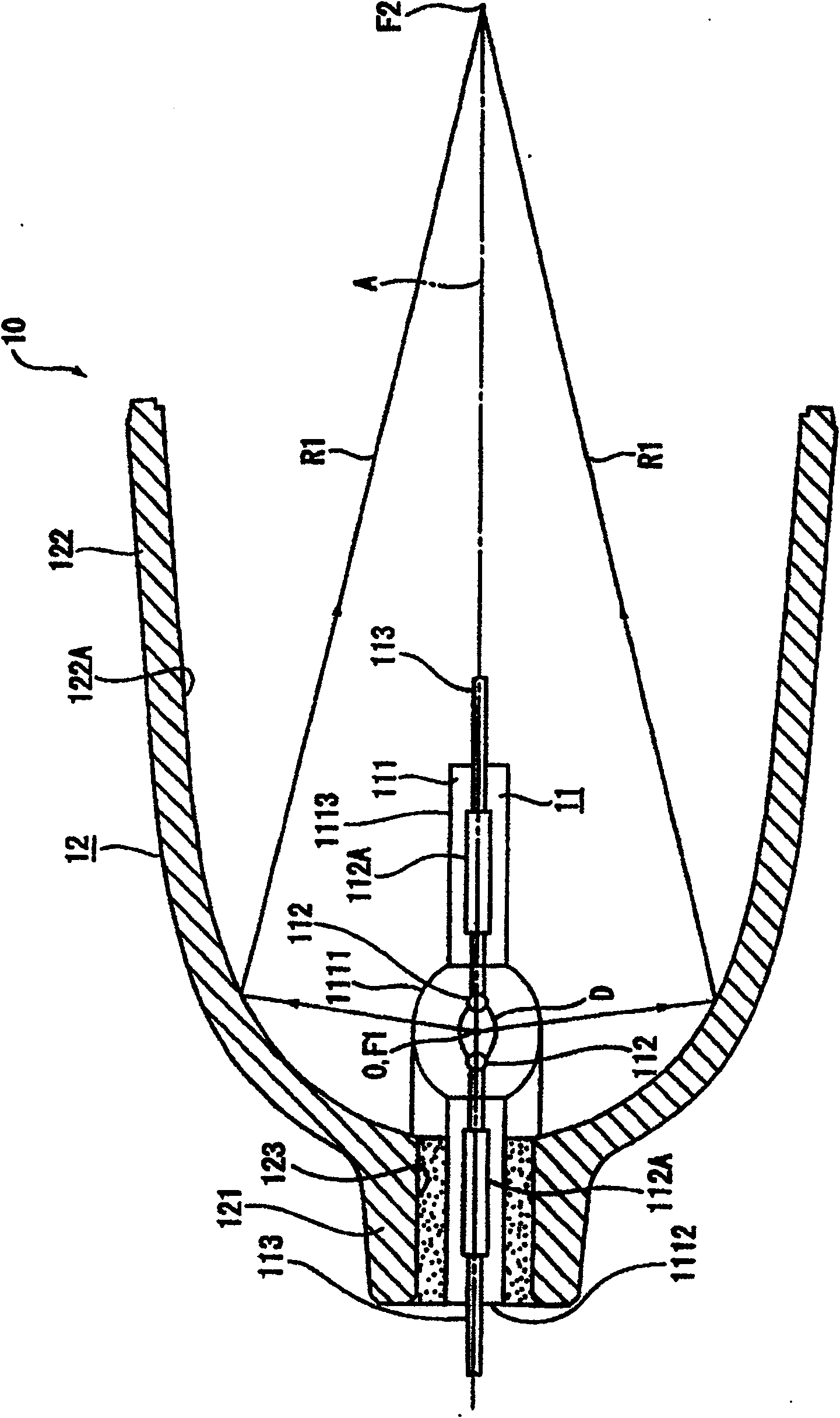
[0252] In the first embodiment described above, the light source device 10 is composed of the light source lamp 11 and the main reflector 12 .
[0253] On the other hand, in the second embodiment, the light source device 10A includes, in addition to the light source lamp 11 described in the above-mentioned first embodiment, a reflector whose shape is different from that of the main reflector 12 described in the above-mentioned first embodiment. The main mirror 12A and the sub-mirror 13. Other configurations are the same as those of the first embodiment described above.
[0254] Figure 10 and Figure 11 It is a sectional view showing a schematic c...
Embodiment 3
[0313] Next, Embodiment 3 of the present invention will be described with reference to the drawings.
[0314] In the following description, the same structures and components as those of the above-mentioned first embodiment and the above-mentioned second embodiment are given the same reference numerals to omit or simplify their detailed descriptions.
[0315] In the above-mentioned Example 1 and the above-mentioned Example 2, after the blank tube 111' was formed by blow molding, it was manufactured by machining the vicinity of the boundary between the light-emitting part 1111 and the sealing parts 1112 and 1113 of the blank tube 111'. Light emitting tube 111.
[0316] On the other hand, in Example 3, the light pipe 111A is produced by blow molding so as to satisfy the relationship of Expression 26 described in the above-mentioned Example 1, or the relationship of Expression 34 and Expression 37 described in the above-mentioned Example 2. That is, this embodiment is only diffe...
PUM
 Abstract
Description
Claims
Application Information
 - R&D
- Intellectual Property
- Life Sciences
- Materials
- Tech Scout
- Unparalleled Data Quality
- Higher Quality Content
- 60% Fewer Hallucinations
Browse by: Latest US Patents, China's latest patents, Technical Efficacy Thesaurus, Application Domain, Technology Topic, Popular Technical Reports.
© 2025 PatSnap. All rights reserved.Legal|Privacy policy|Modern Slavery Act Transparency Statement|Sitemap|About US| Contact US: help@patsnap.com