Manufacturing method for valve seat assembly

A manufacturing method and valve seat technology, applied in refrigeration components, lift valves, valve details, etc., can solve problems such as low processing efficiency, complex structure, looseness, etc., to ensure product quality, avoid interference and collision, and improve reliability.

Inactive Publication Date: 2012-08-01
ZHEJIANG SANHUA INTELLIGENT CONTROLS CO LTD
View PDF9 Cites 7 Cited by
  • Summary
  • Abstract
  • Description
  • Claims
  • Application Information

AI Technical Summary

Problems solved by technology

There are following deficiencies in this connection method: a) The riveting structure between the valve seat 2' and the cover 3' needs to be provided with a specific flange 2'1 on the valve seat 2', and the part structure needs to be specially designed, resulting in The structure is complex, the processing efficiency is low, and the cost is high; b) When the flange 2'1 is riveted with the cover 3', it is difficult to position the valve seat 2' and the cover 3'. After riveting, the valve seat 2' and the cover The coaxiality of the cover 3' is difficult to be precisely controlled; c) when the valve seat 2' and the cover 3' are placed in a furnace for brazing, the gap between the flange 2'1 of the valve seat 2' and the cover 3' The riveting structure between the two will cause looseness between the flanging 2'1 and the cover 3' due to the different expansion coefficients of the materials and the change of the stress between the two, resulting in low reliability of the riveting positioning, thus affecting the valve seat 2 ' and the coaxiality between the cover 3'

Method used


Image

  • Manufacturing method for valve seat assembly
  • Manufacturing method for valve seat assembly
  • Manufacturing method for valve seat assembly

Examples


Embodiment Construction

[0044] The core of the present invention is to provide a manufacturing method of the valve seat assembly, which can not only position the valve seat and the cover more conveniently, but also ensure the coaxiality between the valve seat and the cover.

[0045] In order to enable those skilled in the art to better understand the technical solutions of the present invention, the present invention will be further described in detail below in conjunction with the accompanying drawings and specific embodiments.

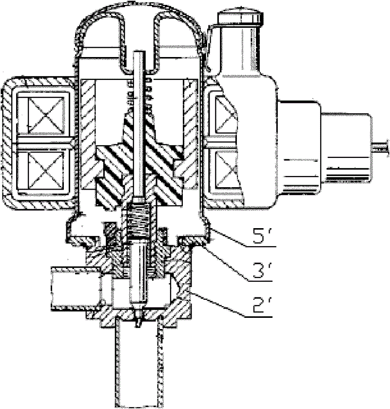
[0046] Please refer to Figure 4 , Figure 4 It is a schematic structural diagram of an electronic expansion valve in an embodiment of the present invention.

[0047] Such as Figure 4As shown, the electronic expansion valve includes a valve seat 2, and the valve seat 2 is connected to the casing 53 through the cover 3; the casing 53 is provided with a magnet 54, and the magnet 54 is fixedly connected with the screw rod 55, and rotates along with the magnet 54 in a circum...


PUM


Abstract

The invention discloses a manufacturing method for a valve seat assembly, which is used for assembling a valve seat (2) and a cover (3) of an electronic expansion valve together to form a valve seat assembly. The manufacturing method comprises the following steps of: (11) fixedly joining the cover (3) with the valve seat (2) in a braze soldering way; and (12) processing a positioning part on the cover (3) to be assembled with a shell (53) of the electronic expansion valve by adopting the circumferential outer diameter of the valve seat (2) as a positioning benchmark. In specific, following the step (12), the manufacturing method also comprises the following steps of: (13) respectively soldering a first connecting pipe (51) and a second connecting pipe (52) of the electronic expansion valve inside a first connecting hole (25) and a second connecting hole (26) of the valve seat (2), and ensuring the soldering temperature to be lower than the temperature of the braze soldering between the valve seat (2) and the cover (3). According to the manufacturing method, not only are the valve seat (2) and the cover (3) convenient to position, but also the proper alignment between the valve seat (2) and the cover can be ensured.

Description

technical field [0001] The invention relates to the technical field of electronic expansion valves, in particular to a method for manufacturing a valve seat assembly of an electronic expansion valve. Background technique [0002] In refrigeration automatic control components, such as electronic expansion valves, the connection between the valve seat and the shell is very important. It is necessary to ensure the coaxiality of the two and the airtightness of the connection between the two. In the prior art, the connection between the valve seat and the shell generally uses a cover as an intermediate transition method. In this connection method, the connection between the cover and the valve seat is generally assembled by gap riveting and then brazed in the furnace to reliably connect the two. It is difficult to ensure the coaxiality of the two. On the other hand, the solder will penetrate into the gap between the cover and the valve seat during brazing, which will cause the p...

Claims


Application Information

Patent Timeline
Patent Type & Authority Applications(China)
IPC IPC(8): F16K27/10F16K1/42F25B41/06
CPCY02B30/72Y02B30/70
Inventor 詹才意魏先让
Owner ZHEJIANG SANHUA INTELLIGENT CONTROLS CO LTD
Why Eureka
Try Eureka