
Extreme-ultraviolet-projection photoetching objective lens

A projection light, extreme ultraviolet technology, applied in microlithography exposure equipment, optics, optical components, etc., can solve the problems of reduced field of view lithography performance, reduced optical modulation transfer function, reduced lithography performance, etc., to achieve excellent imaging. quality, improve lithography resolution, reduce the difficulty of processing and inspection

Active Publication Date: 2012-07-25
BEIJING INSTITUTE OF TECHNOLOGYGY
View PDF9 Cites 5 Cited by
  • Summary
  • Abstract
  • Description
  • Claims
  • Application Information

AI Technical Summary

Problems solved by technology

The problem is that the angle of incidence of light on the mirrors is too large, and in some structures the angle of incidence of light on some mirrors exceeds 24°
A large incident angle of light will cause the multi-layer reflective film coated on the mirror to cause significant phase and amplitude changes of the reflected light, resulting in a decrease in lithography performance
[0007] The existing 6-mirror design US patent US6188513, in which part of the objective lens design has an optical path obstruction, resulting in a decrease in the optical modulation transfer function (MTF) of some fields of view, resulting in a decrease in the lithography performance of this part of the field of view

Method used


Image

  • Extreme-ultraviolet-projection photoetching objective lens
  • Extreme-ultraviolet-projection photoetching objective lens
  • Extreme-ultraviolet-projection photoetching objective lens

Examples


Embodiment 1

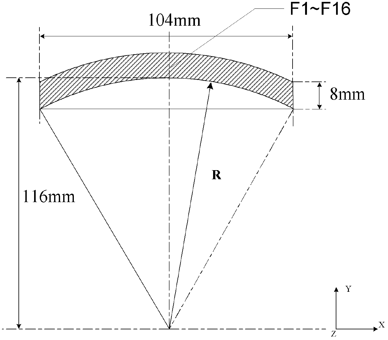
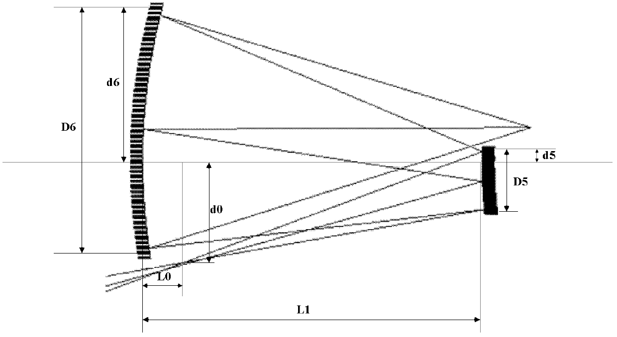
[0052] The extreme ultraviolet projection lithography objective lens of the present invention includes a first mirror group and a second mirror group, and the first mirror group includes a circular diaphragm and four reflecting mirrors, wherein the four reflecting mirrors are respectively the first reflecting mirror M1 and the second reflecting mirror. Two reflecting mirrors M2, the third reflecting mirror M3 and the fourth reflecting mirror M4, the second mirror group includes two reflecting mirrors, which are respectively the fifth reflecting mirror M5 and the sixth reflecting mirror M6; The positional relationship between the circular diaphragms is: first mirror M1, circular diaphragm, second mirror M2, third mirror M3, fourth mirror M4, fifth mirror M5, sixth mirror M6 .

[0053] Table 1 shows the specific design parameters of each lens in this embodiment; a negative sign in front of the radius value indicates that the center of curvature of the lens is located on the left...


PUM


Abstract

The invention provides an extreme-ultraviolet-projection photoetching objective lens with a six-reflector structure. A first reflector M1, a circular diaphragm, a second reflector M2, a third reflector M3 and a fourth reflector M4 are arranged in a first reflector group, and a fifth reflector M5 and a sixth reflector M6 are arranged in a second reflector group; the first reflector group is used for forming an intermediary image between the fifth and sixth reflectors from an object plane; the second reflector group is used for forming an image on an image plane from the intermediary image so as to realize the 1 / 4 objective image narrowing power of a system; and the sixth reflector M6 does not shelter emergent light of the first reflector group, and the fifth reflector M5 does not shelter reflected light of the sixth reflector M6. According to the invention, through an improvement on the fifth and sixth reflectors, the fifth and sixth reflectors can form the image on the image plane of the extreme-ultraviolet-projection photoetching objective lens from the intermediary image without sheltering.

Description

technical field [0001] The invention relates to an extreme ultraviolet projection lithography objective lens, which can be used in a scanning-step extreme ultraviolet lithography system and belongs to the technical field of optical design. Background technique [0002] As the most promising next-generation lithography technology, extreme ultraviolet lithography is expected to meet the industrialization requirements of semiconductor manufacturing at 32nm and higher technology nodes. Extreme ultraviolet lithography uses a light source with a wavelength of 11-15nm for illumination. Since almost all optical materials have strong absorption in this wavelength band, the extreme ultraviolet lithography system uses reflective optical components coated with reflective films. As the core component of the extreme ultraviolet lithography system, the extreme ultraviolet projection lithography objective lens has the design requirements of high resolution, high image quality and large fiel...

Claims


Application Information

Patent Timeline
IPC IPC(8): G02B17/06G02B13/18G03F7/20
Inventor 李艳秋曹振刘菲
Owner BEIJING INSTITUTE OF TECHNOLOGYGY
Learn More