
Uninterruptible direct current power supply method and device

A technology of DC power supply and DC voltage, applied in the direction of circuit devices, electrical components, emergency power supply arrangements, etc., can solve problems such as power failure or drop of DC output voltage, influence of DC electrical equipment, different power failure or drop, etc., to achieve switching Simple switch control, simple and reliable switching mode

Active Publication Date: 2012-07-11
BEIJING GENERAL RES INST OF MINING & METALLURGY
View PDF4 Cites 4 Cited by
  • Summary
  • Abstract
  • Description
  • Claims
  • Application Information

AI Technical Summary

Problems solved by technology

[0005] The disadvantages of the method for switching between the grid power supply line and the battery power supply line of the above-mentioned uninterruptible DC power supply equipment in the prior art are: due to the long delay of the relay switch in the process of turning off and on and the delay of the detection line , it will cause instantaneous power-off or drop of the DC output voltage, and due to the inconsistency of device characteristics, the power-off or drop situation will also be different, which will have a certain impact on the DC power equipment

Method used


Image

  • Uninterruptible direct current power supply method and device
  • Uninterruptible direct current power supply method and device
  • Uninterruptible direct current power supply method and device

Examples


Embodiment 1

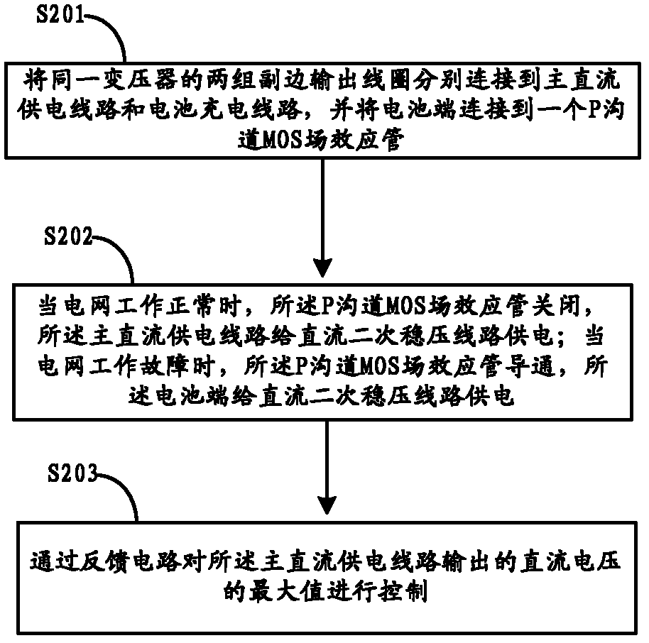
[0019] A schematic diagram of the implementation principle of an uninterrupted DC power supply method provided in the embodiment is as follows: figure 1 As shown, the specific processing flow is as follows figure 2 As shown, the following processing steps are included:

[0020] Step S201 , connect two sets of secondary output coils of the same transformer to the main DC power supply line and the battery charging line respectively, and connect the battery terminal to a P-channel MOS (metal insulator semiconductor, metal insulator semiconductor) field effect transistor.

[0021] Connect the first group of secondary output coils S1 of the transformer to the input end of the main DC power supply line, and the output end of the main DC power supply line is connected to the input end of the DC secondary voltage stabilization line (DC-DC unit), and the The second group of secondary output coils S2 of the transformer is connected to the input terminal of the battery charging circuit...

Embodiment 2

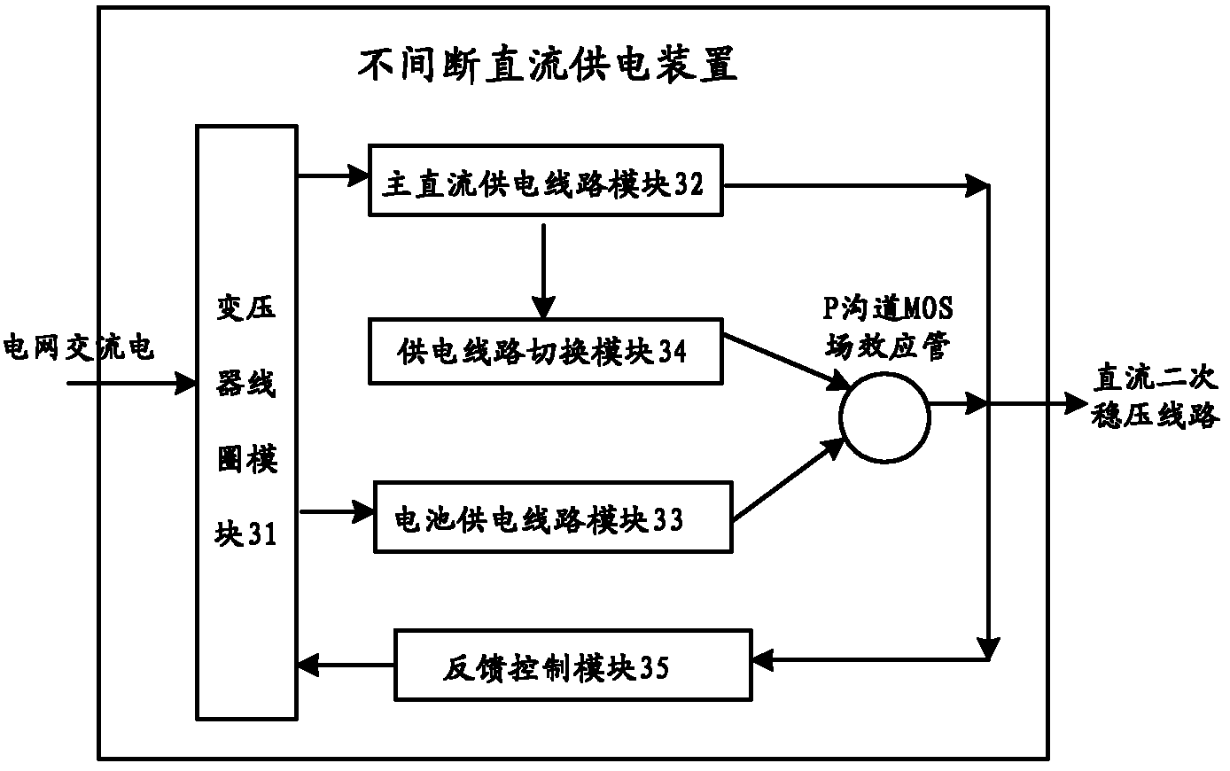
[0035] The implementation circuit schematic diagram of an uninterruptible DC power supply device provided by this embodiment is as follows: figure 1 As shown, the specific structure diagram is shown in image 3 As shown, the following modules are included:

[0036] The transformer coil module 31 is used to connect the first set of secondary output coils of the transformer to the input end of the main DC power supply line, and connect the second set of secondary output coils of the transformer to the input end of the battery charging line;

[0037] The main DC power supply line module 32 is used to connect the output end of the main DC power supply line to the input end of the DC secondary voltage stabilization line. When the power grid is working normally, it will receive The AC voltage from the grid is converted into a DC voltage, and the DC voltage is transmitted to the input terminal of the DC secondary voltage stabilization line;

[0038] The battery power supply circuit...


PUM


Abstract

The invention relates to an uninterruptible direct current power supply method and an uninterruptible direct current power supply device. The rectification output of two groups of secondary output coils of a transformer is respectively taken as a main direct current power supply line and a battery power supply line, a battery end is connected to a source of a P-channel metal oxide semiconductor (MOS) field effect transistor, and a drain of the P-channel MOS field effect transistor is connected to an input end of a direct current secondary voltage-stabilizing line. When a grid normally works, the main direct current power supply line converts a received alternating current voltage into a direct current voltage and transmits the direct current voltage to the direct current secondary voltage-stabilizing line, the battery power supply line converts the received alternating current voltage into the direct current voltage, a battery is charged, and the P-channel MOS field effect transistor is in a turn-off state. When the grid fails, the P-channel MOS field effect transistor is in a turn-on state, the direct current voltage which is output by the battery end is transmitted to the direct current secondary voltage-stabilizing line through the P-channel MOS field effect transistor. According to the embodiment of the invention, the main direct current power supply line and the battery power supply line are switched simply and reliably, and instant power-failure or dip of a direct current output voltage is avoided.

Description

technical field [0001] The invention relates to the technical field of industrial application, in particular to an uninterrupted direct current power supply method and device. Background technique [0002] In the mine online safety monitoring system, due to the special environment of the mine, there are often extremely harsh conditions such as high temperature, dusty, high humidity, high cold, lightning, etc. At the same time, there are practical problems such as frequent power outages and repeated damage to power supply lines. The reliability of mine online safety monitoring system, especially the reliability of power supply, has become one of the focus issues in the industry. At the same time, the more dangerous the situation, the worse the reliability of the online safety monitoring system. This problem greatly limits the application range of the online safety monitoring system in mines, and also buryes hidden dangers for mine safety production. In this application backg...

Claims


Application Information

Patent Timeline
IPC IPC(8): H02J9/06
Inventor 陆得盛张达杨小聪余斌张元生刘建东余乐文王利岗陈凯杨喜迎金枫
Owner BEIJING GENERAL RES INST OF MINING & METALLURGY
Learn More