Liquid metal knife cutting system

A liquid metal, cutting system technology, applied in metal processing equipment, abrasives, abrasive jet machine tools, etc., can solve problems such as high noise and easy wear, and achieve the effect of reducing industrial water use

Active Publication Date: 2012-07-11
TECHNICAL INST OF PHYSICS & CHEMISTRY - CHINESE ACAD OF SCI
View PDF5 Cites 4 Cited by
  • Summary
  • Abstract
  • Description
  • Claims
  • Application Information

AI Technical Summary

Problems solved by technology

However, the traditional pumps are all mechanical pumps, which are noisy and prone to wear and tear.

Method used


Image

  • Liquid metal knife cutting system
  • Liquid metal knife cutting system
  • Liquid metal knife cutting system

Examples


Embodiment 1

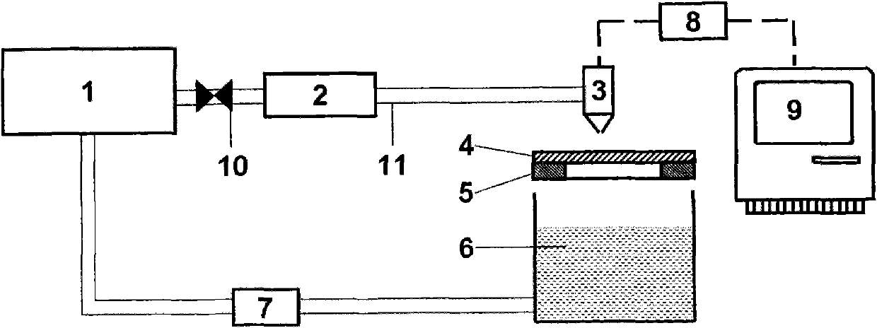
[0042] image 3 It is the structural representation of the liquid metal knife cutting system (embodiment 1) of the present invention; Fig. 1 (b) is the structural representation of cutting device 3; As can be seen from the figure, the liquid metal knife cutting system of the present embodiment comprises: a built-in A liquid metal storage tank 1 for liquid metal, a booster pump 2, a cutting device 3, a workbench 5, a liquid metal recovery container 6 and a numerical control table 9;

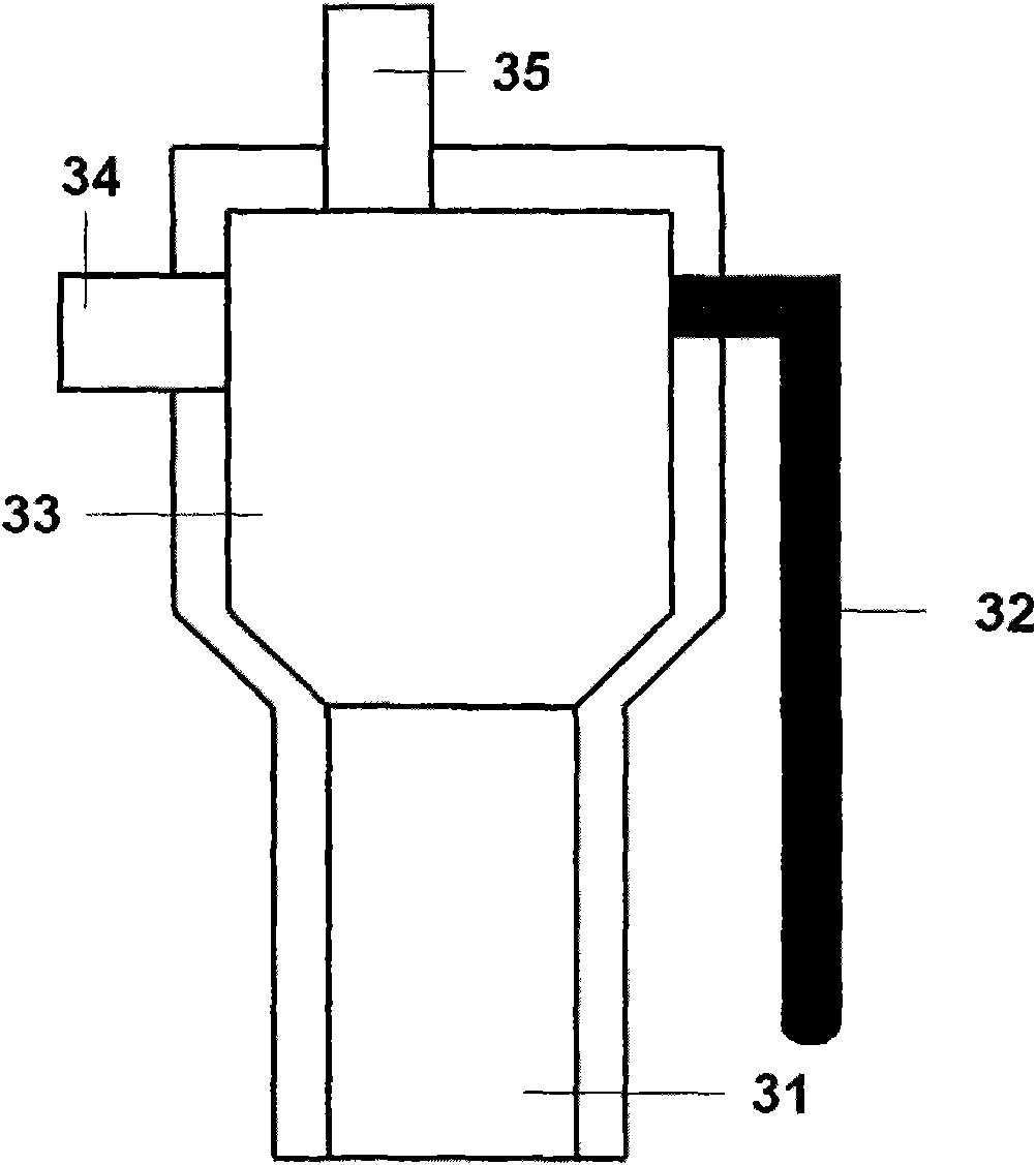
[0043] Such as figure 2 As shown, the cutting device 3 includes:

[0044] A cutting nozzle 31 with a diameter of 0.01-10 mm and a rectifying cavity 33 connected to the upper end of the cutting nozzle 31; the rectifying cavity 33 is a trapezoidal cavity with a large upper volume and a small lower volume; There is a liquid metal inlet pipe 34 communicating with the outlet of the booster pump 2 through a flexible silicone tube 11; an observation hole is also opened on the side wall of the rectifyin...

Embodiment 2

[0052] Fig. 1 (a) is the structural representation of the liquid metal knife cutting system of the present embodiment; Fig. 1 (b) is the structural representation of cutting device 3; As can be seen from the figure, the liquid metal knife cutting system of the present embodiment is different from Embodiment 1 What is more: also includes the abrasive material inlet pipe 35 that is installed on the upper part of the rectifying chamber 33, the abrasive material inlet pipe 35 communicates with the abrasive material feeder 12 with the abrasive material control valve 13; the liquid metal recovery container 6 is connected with the recovery pump 7 is equipped with a liquid-solid separation device 14 communicating with the abrasive feeder 12 on the connecting pipeline connected with each other.

Embodiment 3

[0054] image 3 It is the structural representation of the liquid metal knife cutting system of the present embodiment; Fig. 1 (b) is the structural representation of the cutting device 3; As can be seen from the figure, the liquid metal knife cutting system of the present embodiment is different from Embodiment 2 in that it also includes The vacuum cover 15 installed on the workbench 5 covers the workpiece 4 to be cut and the cutting nozzle 31 placed on the workbench 5 .


PUM


Abstract

A liquid metal knife cutting system comprises a cutting device, wherein the cutting device comprises a cutting nozzle and a rectification cavity communicated with the upper end of the cutting nozzle. An inlet pipe communicated with the pressure pump outlet through a hose is installed on the lateral wall of the rectification cavity, a miniature camera is installed on an observation hole on the lateral wall of the rectification cavity, and the pressure pump inlet is communicated with the liquid metal storage tank outlet. A workbench is arranged below the cutting nozzle, a recycle container is arranged below the workbench, a connection pipeline at the lower portion of the recycle container is communicated with the storage tank bottom, and a recycle pump is installed on the pipeline of the recycle container. A numerical control table comprises a processor and a data base, wherein the processor is used for calculating relevant cutting parameters in cutting, and the data base is used for recording the cutting parameters corresponding to cutting materials and cutting results. The cutting nozzle of the cutting device is coaxial with a motor shaft, and a motor receives operation commands given out by the numerical control table and controls a cutting path of the cutting nozzle of the cutting device according to the commands to complete cutting of a workpiece to be cut. The cutting system is high in cutting accuracy, stable, low in noise, energy-saving and environment-friendly.

Description

technical field [0001] The invention relates to a high-pressure liquid metal knife cutting system, in particular to a high-pressure liquid metal knife cutting system which adopts liquid metal as a cutting working fluid and cuts workpieces after being pressurized by an electromagnetic pressure pump. Background technique [0002] Human beings have used the impact force of fluid since ancient times to manufacture water conservancy machinery such as waterwheels and water mills. And if the fluid is ejected from the high-pressure nozzle, a greater impact force will be generated. Inspired by this, former Soviet scientists developed high-pressure water jet cutting technology. Compared with electric saw, electric arc cutting and laser cutting, fluid cutting has many advantages. It is extremely fast and can cut various workpieces according to user needs; secondly, the processing is cold processing, so there is no need to worry about the burning and deformation of the workpiece cause...

Claims


Application Information

Patent Timeline
Patent Type & Authority Applications(China)
IPC IPC(8): B24C3/00
Inventor 刘静马璐
Owner TECHNICAL INST OF PHYSICS & CHEMISTRY - CHINESE ACAD OF SCI
Why Eureka
Try Eureka