
rotary tool

A technology of rotating tools and rotating bodies, which is applied in the direction of manufacturing tools, metal processing equipment, and cutting tools of sawing machines, and can solve problems such as easy burrs at the corners

Inactive Publication Date: 2016-07-13
KOBAYASHI DAI LTD
View PDF4 Cites 0 Cited by
  • Summary
  • Abstract
  • Description
  • Claims
  • Application Information

AI Technical Summary

Problems solved by technology

[0003] When V-groove processing is performed on a printed circuit board or the like using this diamond blade saw 1, burrs are likely to occur at the corners after V-cutting.

Method used


Image

  • rotary tool
  • rotary tool
  • rotary tool

Examples


Embodiment Construction

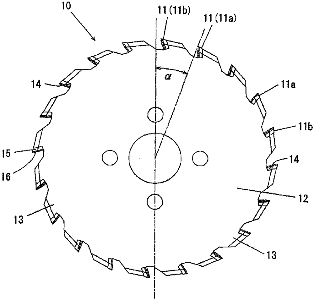
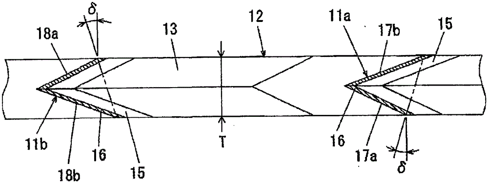
[0085] Hereinafter, the form for implementing this invention is concretely demonstrated based on drawing. Such as figure 1 , figure 2 As shown, the rotary tool 10 according to the first embodiment of the present invention is a rotary tool having inverted V-shaped pieces 11 (11a, 11b) on the outer periphery of a disk-shaped rotary body (base member) 12 along the circumferential direction. Serrated edge lands 13 are formed at equal intervals. The blade base 13 is formed in an inverted V-shape when viewed from the front, and a mounting portion 14 notched into an L-shape when viewed from the side is formed on the side of the rotation direction surface of the blade base 13 , and an inverted V-shape is fixed to the mounting portion 14 . Sheet 11 (11a, 11b). The inverted V-shaped piece 11 has a polycrystalline diamond layer (PCD layer) 16 on the front side of the cemented carbide layer 15, and the PCD layer 16 is placed on the mounting part 14 toward the side of the rotation dir...


PUM


Abstract

To provide a rotary tool capable of performing V-groove processing or end face cutting of a substrate in one process while suppressing the generation of burrs. On the outer periphery of the disc-shaped base member, sawtooth-shaped blades are formed at predetermined intervals in the circumferential direction, and the blades are formed into an inverted V shape when viewed from the front, and a mounting portion is formed on the side of the rotation direction of the blade base. The inverted V-shaped piece is fixed on the mounting part when viewed from the front, and the inverted V-shaped piece is composed of a first inverted V-shaped piece with a lead angle on one inclined edge side and a second inverted V-shaped piece with a lead angle on the other inclined edge side. Shaped sheet configuration, the inclination angle of the other inclined evasion edge of the first inverted V-shaped sheet relative to the center line is formed smaller than the inclination angle of one inclined edge, and the second inverted V-shaped sheet is formed so that it is opposite to the center line when viewed from the front. The first inverted V-shaped pieces are bilaterally symmetrical, and the first inverted V-shaped pieces and the second inverted V-shaped pieces are arranged alternately along the circumferential direction.

Description

technical field [0001] The present invention relates to a rotary tool for forming a V-shaped groove on a printed circuit board, an aluminum substrate, a copper substrate, or the like, or for cutting an end surface of a substrate. Background technique [0002] Conventionally, a diamond blade saw used when forming a V-shaped notch in a workpiece such as a printed circuit board is known. The blade saw 1 as Figure 18 As shown, on the sheet fixing recess 3 provided on the outer peripheral edge of the circular saw base plate 2, welding and fixing such as Figure 19 The pieces 4 shown are V-cut at an angle α=about 30 degrees, and the diamond layer 5 of the pieces 4 is fixed on the entire surface on the rake surface 6 side of each piece 4 . [0003] When V-groove processing is performed on a printed circuit board or the like using this diamond blade saw 1 , burrs are likely to be generated at corners after V-cutting. Therefore, a diamond blade saw that does not easily generate bu...

Claims


Application Information

Patent Timeline
Patent Type & Authority Patents(China)
IPC IPC(8): B23D61/04
Inventor 小林修
Owner KOBAYASHI DAI LTD
Learn More