Steam sterilization device with control valves
A steam sterilization and control valve technology, applied in heating and other directions, can solve the problems of material leakage, easy sealing of valve body and gate plate, easy accumulation of material in control valve, etc., and achieve the effect of ensuring stability
- Summary
- Abstract
- Description
- Claims
- Application Information
AI Technical Summary
Problems solved by technology
Method used
Image
Examples
Embodiment 1
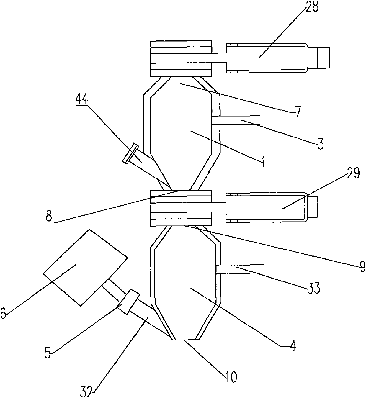
[0064] figure 1 A steam sterilization device provided with a control valve according to the present invention is provided, including a sterilization chamber 1 and a cooling chamber 4, and a sterilization chamber is respectively arranged on the sterilization chamber 1 and the cooling chamber 4 Feed inlet 7, sterilization bin outlet 8, cooling bin inlet 9 and cooling bin outlet 10, a hot air inlet 44 is arranged at the bottom of the sterilization bin 1, the upper part of the sterilization bin 1 A gas discharge port 3 is provided;
[0065] The cooling bin 4 is also provided with a cooling bin air inlet 32 and a cooling bin air outlet 33, the cooling bin air inlet 32 is located at the bottom of the cooling bin 4, and the cooling bin air outlet 33 is located at the top of the cooling bin 4, so The air inlet 32 of the cooling bin is connected with the refrigerator 6 through the inlet control valve 5 of the cooling bin;
[0066] A first control valve 28 is connected to the up...
Embodiment 2
[0077] The steam sterilizer provided with the control valve described in this embodiment is as follows: Figure 4 As shown, the difference between the sterilizing device described in this embodiment and the sterilizing device described in Embodiment 1 is that the hot air inlet 44 is also provided with a first branch air inlet 14 and a second branch air inlet 15. The first branch air inlet 14 is connected to the heat exchanger 18 through the first passage 161 of the three-way control valve 16, and the second branch air inlet 15 is connected to the heat exchanger 18 through the pulse control valve 11, The heat exchanger 18 is connected to the hot air induced fan 19 and the steam generator 17 , and the second passage 162 of the three-way control valve is connected to the hot air induced fan 19 .
[0078] The gas discharge port 3 is arranged on the upper side wall of the sterilization chamber 1, and a filter connected to the inner wall of the sterilization chamber 1 is arranged in...
Embodiment 3
[0086] The steam sterilization device provided with the control valve described in this embodiment is as follows: Figure 7 As shown, compared with Example 2, the steam sterilization device in this embodiment is further provided with a feed hopper 27 at the feed port of the sterilization bin 1, and the feed hopper 27 and the feed port 7 of the sterilization bin They are connected through the first control valve 28, so as to facilitate the addition of materials. A hopper is provided at the discharge port 10 of the cooling bin, and a third control valve 31 is connected between the hopper and the discharge port 10 of the cooling bin.
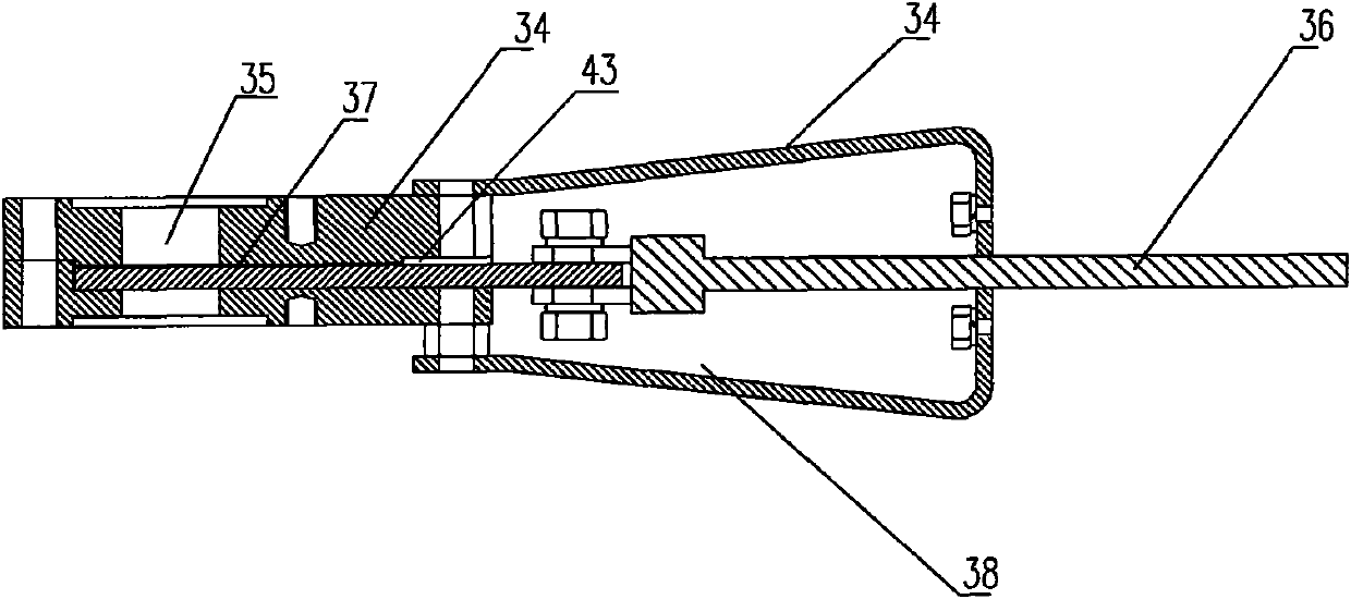
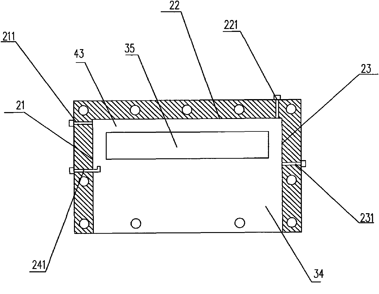
[0087] The steam sterilizing device in this embodiment can also be based on the above, and a filter screen 34 and a pulse device 35 for blowing back the filter screen 34 can be set at the cooling cabin air outlet 33 in the cooling cabin 4, and the setting method The function is the same as that of the filter screen 12 and the pulse device 13 in th...
PUM
 Abstract
Description
Claims
Application Information
 - Generate Ideas
- Intellectual Property
- Life Sciences
- Materials
- Tech Scout
- Unparalleled Data Quality
- Higher Quality Content
- 60% Fewer Hallucinations
Browse by: Latest US Patents, China's latest patents, Technical Efficacy Thesaurus, Application Domain, Technology Topic, Popular Technical Reports.
© 2025 PatSnap. All rights reserved.Legal|Privacy policy|Modern Slavery Act Transparency Statement|Sitemap|About US| Contact US: help@patsnap.com


