


Quick Research
Generate reliable direction feasibility study reports for your R&D in just a few steps.

Technical Q&A
Discover and master advanced knowledge NOW. Basics, ideas, possibilities, all at once.

Find Solutions
As an expert in R&D theories, this can generate solutions to your technical problems instantly.

Evaluate Feasibility
Analyze your overall solution with one click, know your potential R&D risks in advance.

Monitor Landscape
Get weekly tech updates, stay abreast of the latest tech innovations and key insights.
Power conversion device
A power conversion device and power conversion technology, applied in the direction of output power conversion devices, electric traction, control devices, etc., can solve the problems of power conversion devices that cannot operate normally or stop, and achieve the goal of suppressing transient oscillation and maintaining normal operation Effect
- Summary
- Abstract
- Description
- Claims
- Application Information
AI Technical Summary
Problems solved by technology
Method used
Image

Examples
Embodiment approach 1
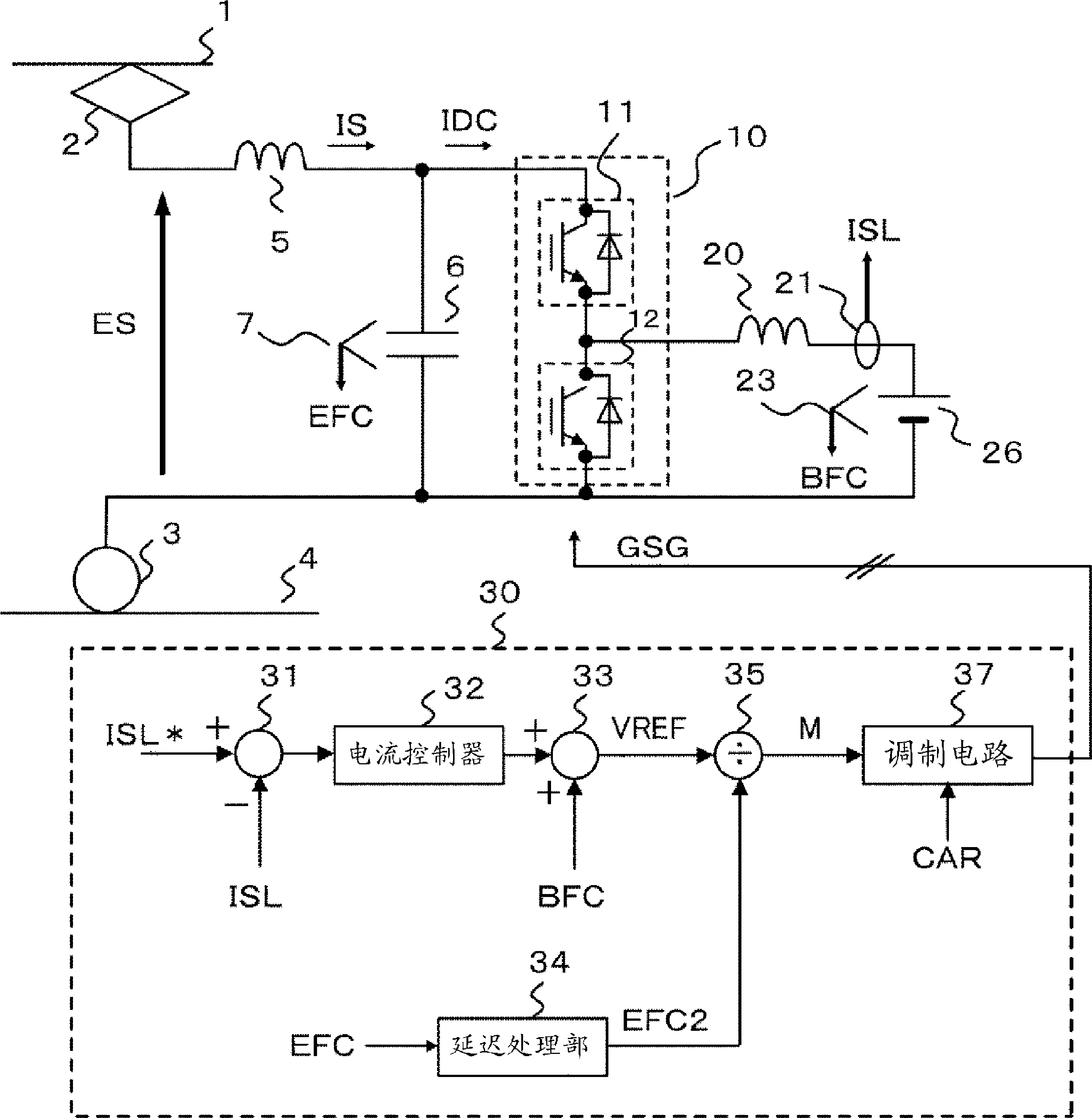
[0022] The first embodiment will be described with reference to the drawings. figure 1 It is a figure which shows the structural example of the power conversion apparatus in Embodiment 1 of this invention. The power conversion device is connected to the overhead line 1 via the power collector 2 and is also connected to the rail 4 via the wheels 3. The overhead line 1 and the rail 4 are connected to a substation (not shown) serving as a DC power source, the current collector 2 receives electric power from the overhead line 1, and the wheels 3 are connected to the rail 4 as a return circuit for return current.
[0023] The power conversion device has: an LC filter circuit consisting of a reactor 5 and a capacitor 6, which is used to suppress the flow of higher harmonic currents to the overhead line 1 side; a voltage detector 7, which detects the DC voltage EFC of the capacitor 6; a power conversion circuit 10 , Connected in parallel with the capacitor 6, composed of the upper arm s...
Embodiment approach 2
[0086] As the power conversion circuit 10, in the first embodiment, a case where a DC-DC converter is used is described, but in the second embodiment, a case where a DC-AC conversion circuit (inverter) is described. In the structure in which the DC-AC conversion circuit is used to drive and control the motor, a negative resistance characteristic is generated on the input side of the power conversion circuit based on the principle explained in the first embodiment.
[0087] Picture 9 It is a figure which shows the structure of the power conversion device in Embodiment 2. The power conversion device is connected to the overhead line 1 via the power collector 2 and is also connected to the rail 4 via the wheels 3. The overhead line 1 and the rail 4 are connected to a substation (not shown) serving as a DC power source, the current collector 2 receives electric power from the overhead line 1, and the wheels 3 are connected to the rail 4 as a return circuit for return current.
[0088...
PUM
 Abstract
Description
Claims
Application Information
 - R&D Engineer
- R&D Manager
- IP Professional
- Industry Leading Data Capabilities
- Powerful AI technology
- Patent DNA Extraction
Browse by: Latest US Patents, China's latest patents, Technical Efficacy Thesaurus, Application Domain, Technology Topic, Popular Technical Reports.
© 2024 PatSnap. All rights reserved.Legal|Privacy policy|Modern Slavery Act Transparency Statement|Sitemap|About US| Contact US: help@patsnap.com