
Dc-dc converter

A technology of DC-DC and conversion device, which is applied in the direction of output power conversion device, conversion of DC power input to DC power output, and adjustment of electric variables.

Active Publication Date: 2011-08-17
NEXGEN CONTROL SYST LLC
View PDF4 Cites 4 Cited by
  • Summary
  • Abstract
  • Description
  • Claims
  • Application Information

AI Technical Summary

Problems solved by technology

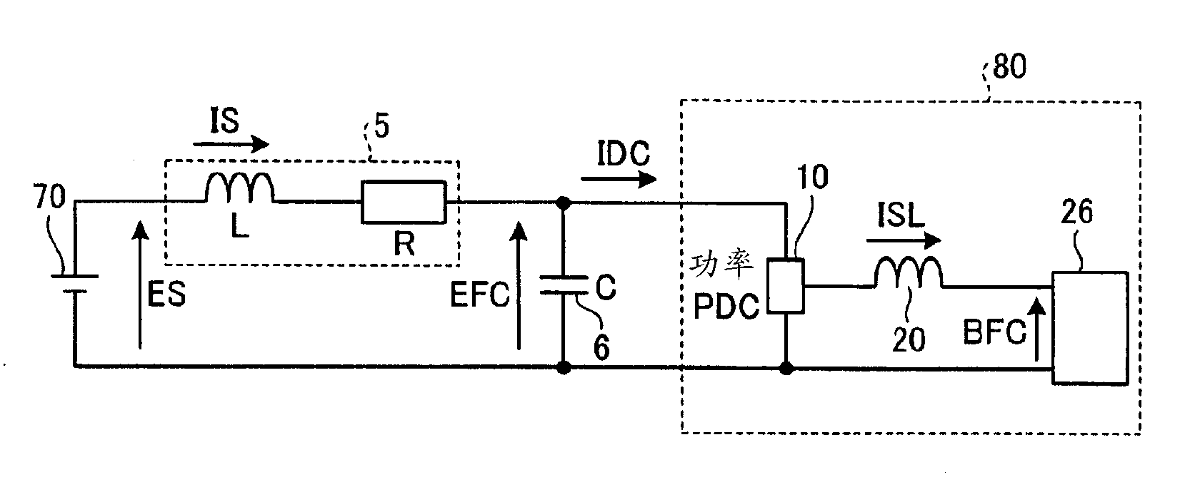
[0005] In addition, although it is not installed in the electric locomotive control device shown in Patent Document 1, in this type of system, a reactor is provided between the DC-DC conversion device and the overhead line, and the reactor and the input capacitor constitute The LC filter circuit attenuates the high-order harmonic current flowing from the DC-DC converter to the overhead line side

Method used


Image

  • Dc-dc converter
  • Dc-dc converter
  • Dc-dc converter

Examples


Embodiment approach 1

[0068] figure 1 It is a diagram showing a configuration example of a DC-DC converter according to Embodiment 1 of the present invention. Such as figure 1 As shown, the DC-DC converter 100 is electrically connected to the overhead line 1 via the power collector 2, and the overhead line 1 is connected to a substation (not shown) serving as a DC power supply. In addition, the DC-DC conversion device 100 is electrically connected to the rail 4 via the wheel 3 serving as a return circuit of the return current, and the rail 4 is connected to a substation.

[0069] The DC-DC converter 100 is configured to include: a main circuit unit 200 ; and a control unit 300 that controls the power flow of the main circuit unit 200 .

[0070] First, the configuration of the main circuit unit 200 will be described. exist figure 1 Among them, the main circuit unit 200 is configured to include, as main components, an input filter circuit 8 , a voltage detector 7 , a switch circuit 10 , a smoothi...

Embodiment approach 2

[0169] In Embodiment 1, in the DC-DC converter configured to function as a control current source that controls the smoothing reactor current ISL flowing through the power storage element so that it becomes a predetermined value, the A control system that suppresses electrical oscillations generated at the resonant frequency of the LC filter and enables stable operation. The DC-DC converter configured to operate by controlling the voltage source is configured with a control system that suppresses electrical oscillations generated at the resonance frequency of the LC filter and enables stable operation.

[0170] Figure 7 It is a diagram showing a configuration example of a DC-DC converter according to Embodiment 2 of the present invention. Such as Figure 7 As shown, the DC-DC conversion device 100a of Embodiment 2 is configured to include: a main circuit unit 200a; and a control unit 300a that controls the power flow of the main circuit unit 200 . In addition, the same cod...


PUM


Abstract

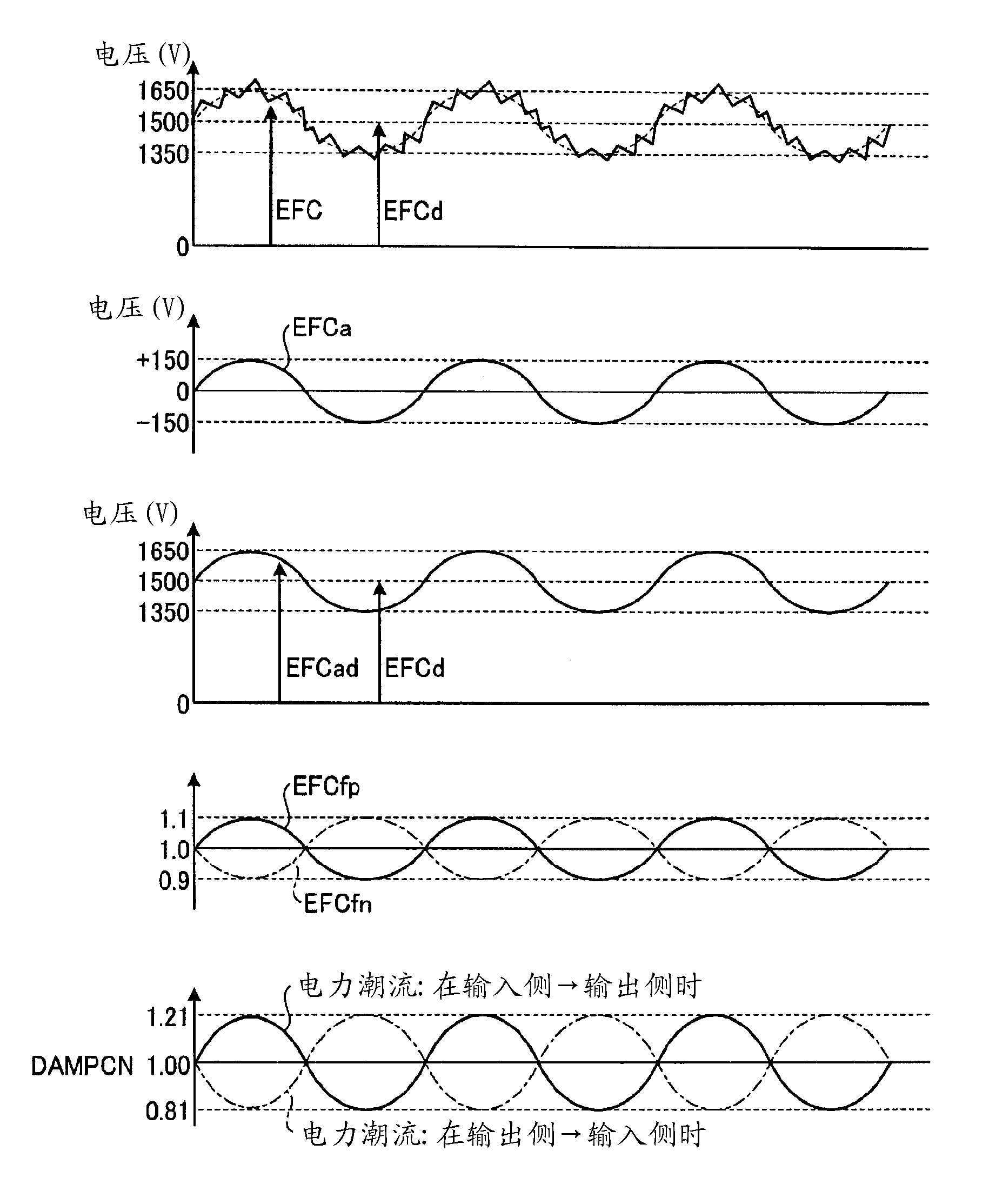
A DC-DC converter comprises a switching circuit (10) having an input end to which an input filter circuit is connected, a smoothing filter circuit (27) consisting of a reactor (5) and a capacitor (6) and connected to the output end of the switching circuit (10), and a control section (300) performing on / off control of the switching circuit (10) by feeding back the quantity of state of the smoothing filter circuit (27). The control section (300) includes a damping control section (40) where the quantity of damping operation for regulating the quantity of state of the smoothing filter circuit (27) is calculated based on the voltage of the capacitor (6).

Description

technical field [0001] The present invention relates to a DC-DC converter suitably applied to, for example, an electric motor car. Background technique [0002] Generally, an electric locomotive adopts a structure in which electric power is collected from overhead lines, third rails, etc. by a current collecting device, and the collected electric power is used to drive a motor. [0003] In recent years, due to the improvement in the performance of power storage elements such as secondary batteries and electric double-layer capacitors, these power storage elements are mounted on electric locomotives, and the collected power is stored in the power storage elements, and the The development of a system that drives a motor by using the electric power stored in the power storage element together with the power collected by the power collector is in progress. [0004] As such a system, there is, for example, an electric locomotive control device disclosed in Patent Document 1 belo...

Claims


Application Information

Patent Timeline
Patent Type & Authority Applications(China)
IPC IPC(8): H02M3/155
CPCH02M3/156H02M2001/0022Y02T10/7216H02M1/14H02M1/0022B60L9/18H02M1/44H02M3/155
Inventor 北中英俊
Owner NEXGEN CONTROL SYST LLC
Learn More