
Ku frequency band low-noise amplifier

A low-noise amplifier and frequency band technology, which is applied in the direction of improving the amplifier to reduce the impact of noise, can solve the problems of troublesome circuit board installation and cavity isolation, processing, and small width and height of the shielding cavity, so as to improve the three-defense capability and reliability, prevent self-oscillation, and increase the effect of isolation

Active Publication Date: 2014-11-19
BEIJING RES INST OF TELEMETRY
View PDF5 Cites 0 Cited by
  • Summary
  • Abstract
  • Description
  • Claims
  • Application Information

AI Technical Summary

Problems solved by technology

[0003] Today's high-performance Ku-band ultra-low noise amplifiers are mostly implemented by hybrid integrated circuits, which can obtain the lowest noise figure, but hybrid integration requires the design of matching circuits, and the circuit board area is large, and the installation and structural design are relatively complicated.
Due to the high frequency of the Ku frequency band, in order to avoid the waveguide transmission mode of the amplifier, the cut-off frequency of the amplifier shielding cavity must be higher than the operating frequency, so the width and height of the shielding cavity are very small, which affects the installation of the circuit board and the cavity. Isolation brings a lot of trouble, it needs to process very complex cavity structure and complex installation process
For example, "A Ku-band Ultra-Low Noise Amplifier" of Chinese Patent Publication No. CN202009363U, the patent discloses a Ku-band ultra-low noise amplifier, which adopts multi-level die integration, film processing technology and carrier board conductive adhesive bonding technology Realization, its process requirements are relatively high, and its structure is complex

Method used


Image

  • Ku frequency band low-noise amplifier
  • Ku frequency band low-noise amplifier
  • Ku frequency band low-noise amplifier

Examples


Embodiment Construction

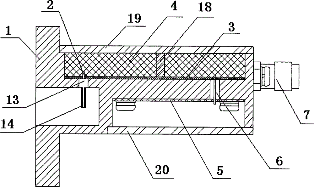
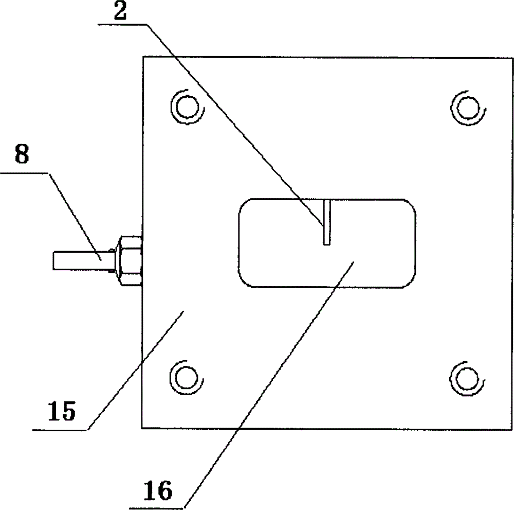
[0020] The present invention simplifies the structure of the amplifier housing 1 by designing independent movable ribs 4 to cooperate with the housing 1; the circuit board and the movable ribs are fixed together by screws, and the circuit board does not need to be welded or bonded, which is convenient for repeated disassembly. The present invention includes a housing 1 , a probe 2 , a radio frequency circuit board 3 , a movable rib 4 , a power board 5 , a DC feeder 6 , a coaxial connector 7 , a feedthrough capacitor 8 and a grounding column 9 .

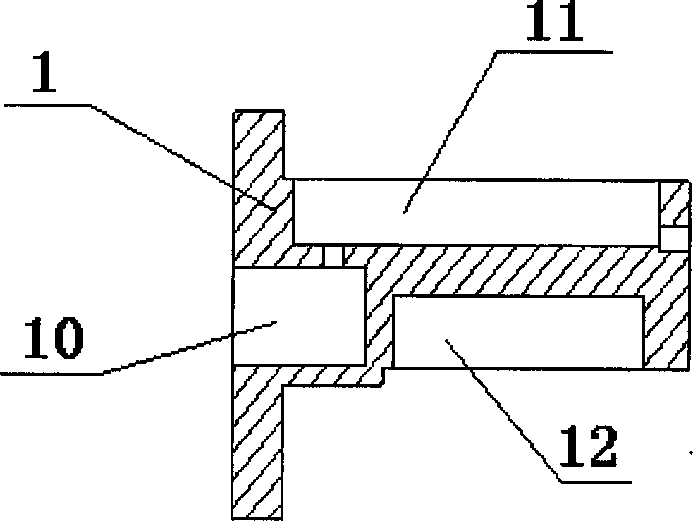
[0021] Such as figure 1 As shown, there are three cavities communicating with the outside world on the shell 1, which serve as the waveguide cavity 10, the upper shielding box 11 and the lower shielding box 12 respectively.

[0022] Such as figure 2 As shown, the probe 2 passes through the transition hole between the upper shielding box body 11 and the waveguide cavity 10 , the upper end of the probe 2 is welded to the radio frequen...


PUM


Abstract

The invention discloses a Ku frequency band low-noise amplifier which comprises a shell, a probe, a radio-frequency circuit board, movable separating tendons, a power supply board, a direct-current feed needle, a coaxial connector, a feed-through capacitor and an earthing rod, wherein the shell is provided with three cavities communicated with the outside, and the three cavities respectively serve as a wave guide cavity, an upper shielding box body and a lower shielding box body; the movable separating tendons are symmetrically distributed above the radio-frequency circuit board, and are fixed in the upper shielding box body together with the radio-frequency circuit board by adopting a demountable static connection mode; the probe penetrates through a transitional pore between the upper shielding box body and the wave guide cavity; the upper end of the probe and the radio-frequency circuit board are welded; the lower end of the probe is positioned in the wave guide cavity; the feed-through capacitor and the power supply board are welded; the earthing rod is connected with the shell; the power supply board is fixed in the lower shielding box body; the direct-current feed needle penetrates through a structure hole between the upper shielding box body and the lower shielding box body, the upper end of the direct-current feed needle and the radio-frequency circuit board are welded, and the lower end of the direct-current feed needle and the power supply board are welded; and the coaxial connector for outputting amplification signals and the radio-frequency circuit board are welded. According to the invention, the structure of the shell of the amplifier is simplified, the mounting of the circuit board is simpler, and the Ku frequency band low-noise amplifier is convenient to dismount repeatedly.

Description

technical field [0001] The invention relates to an amplifier, in particular to a Ku frequency band low noise amplifier. Background technique [0002] Low noise amplifier is an important part in radar, electronic countermeasures, telemetry and remote control, microwave communication and other systems, and its noise figure index directly affects the receiving sensitivity of the system. Therefore, low-noise amplifiers are generally required to have as low a noise figure as possible and a higher gain. In the civil communication market, it is generally required to be easy to manufacture and low in cost. The low noise amplifier can be realized by monolithic integrated circuit or hybrid integrated circuit. Monolithic circuits can achieve the most compact structure and consistency, and in order to obtain better noise performance, you need to use hybrid integrated circuits to achieve. [0003] Today's high-performance Ku-band ultra-low noise amplifiers are mostly implemented by hyb...

Claims


Application Information

Patent Timeline
Patent Type & Authority Patents(China)
IPC IPC(8): H03F1/26
Inventor 周向春
Owner BEIJING RES INST OF TELEMETRY
Learn More