
Thermal management system for low temperature starting of fuel cell power generation system and method thereof

A technology of thermal management system and power generation system, applied in the direction of fuel cell parts, fuel cells, fuel cell additives, etc., can solve the problems of slow increase, slow temperature rise, slow loading speed, etc., and achieve the effect of prolonging the service life

Inactive Publication Date: 2012-06-13
SUNRISE POWER CO LTD
View PDF3 Cites 35 Cited by
  • Summary
  • Abstract
  • Description
  • Claims
  • Application Information

AI Technical Summary

Problems solved by technology

For a chemical reaction, temperature is an important factor affecting its chemical reaction process, so when the fuel cell is at a low temperature, its chemical reaction process will slow down, that is, the performance will deteriorate and the loading speed will slow down
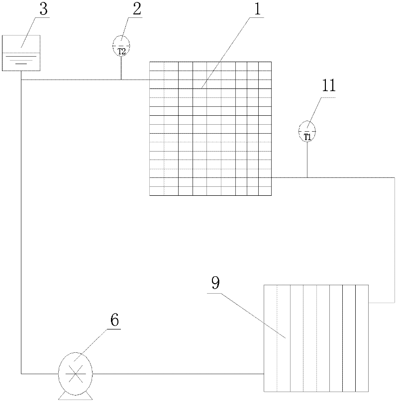
Generally, the thermal management system of a fuel cell power generation system is mainly based on heat dissipation, and the temperature rise of the fuel cell is realized by slowly increasing the waste heat of the fuel cell through the circulation of the cooling fluid. The structure is shown in image 3 , so that the temperature rises slowly and the activity of the catalyst is low, which is not conducive to the improvement of the performance of the fuel cell; at the same time, under the condition of rapid loading at low temperature or excessive load, the activity of the catalyst is low, the voltage drops sharply, and it is easy to break down the electrode and affect the fuel cell. service life

Method used


Image

  • Thermal management system for low temperature starting of fuel cell power generation system and method thereof
  • Thermal management system for low temperature starting of fuel cell power generation system and method thereof
  • Thermal management system for low temperature starting of fuel cell power generation system and method thereof

Examples


Embodiment Construction

[0022] The present invention will be further clearly and completely described below in conjunction with the accompanying drawings. Apparently, the described embodiments are only some of the embodiments of the present invention, rather than all of them. Based on the embodiments of the present invention, all other embodiments obtained by persons of ordinary skill in the art without making creative efforts belong to the protection scope of the present invention.

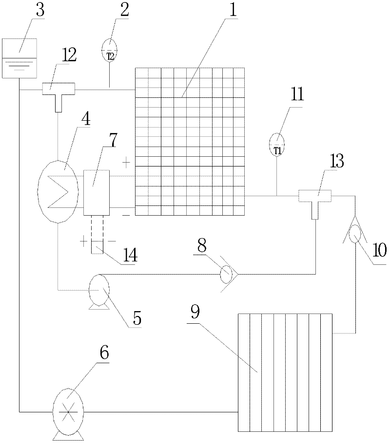
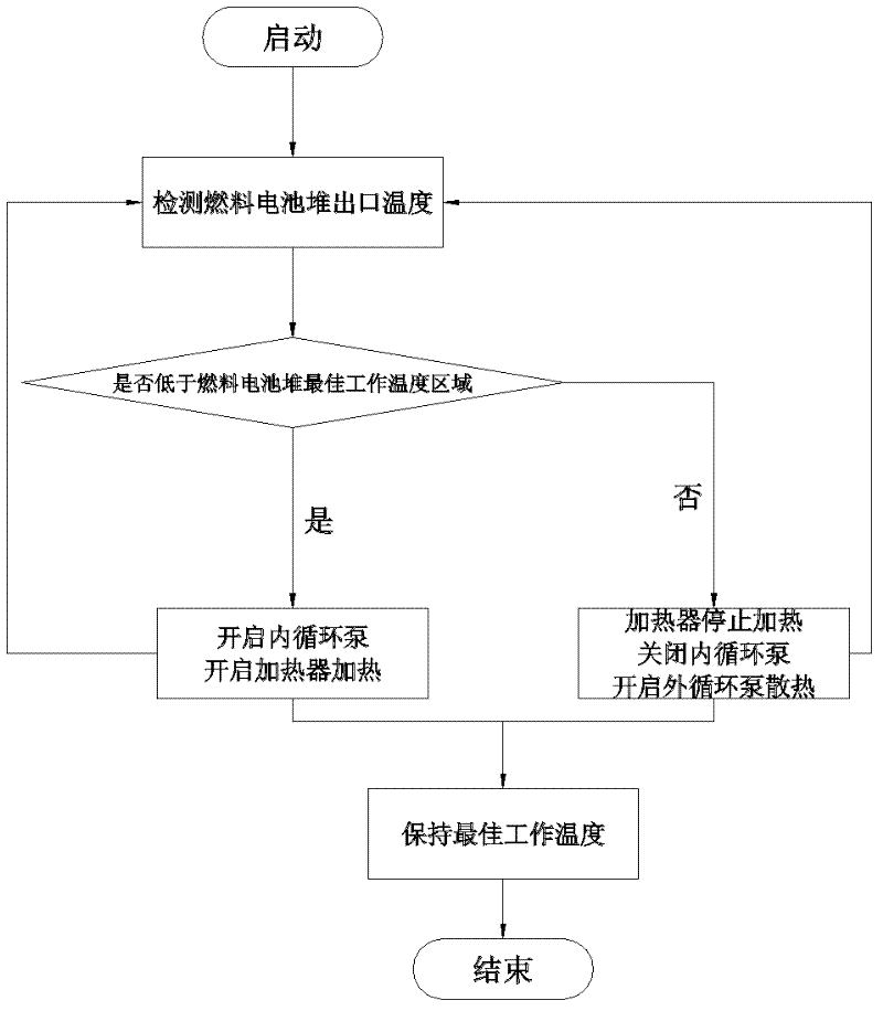
[0023] Such as figure 1 As shown, a low-temperature cold-start thermal management system of a fuel cell power generation system includes an internal circulation heating system and an external circulation cooling system. The internal circulation heating system consists of a fuel cell stack 1 and a fuel cell stack coolant outlet sensor 2 , outlet tee 12, water tank 3, heater 4, internal circulation pump 5, internal circulation check valve 8, inlet tee 13, fuel cell stack coolant inlet sensor 11, the coolant enters the ou...


PUM


Abstract

The invention discloses a thermal management system for low temperature starting of a fuel cell power generation system and a method thereof. The thermal management system comprises an internal circulating heating system and an external circulating cooling system. The internal circulating heating system is composed of a fuel cell stack, a fuel cell stack cooling liquid outlet sensor, an outlet tee, a water tank, a heater, an internal circulation pump, an internal circulation one-way valve, an inlet tee, and a fuel cell stack cooling liquid inlet sensor. And the external circulating cooling system consists of the fuel cell stack, the fuel cell stack cooling liquid outlet sensor, the outlet tee, the water tank, an external circulation pump, a radiator, an external circulation one-way valve, the inlet tee, and the fuel cell stack cooling liquid inlet sensor. By adding an internal circulating heating system, the system of the invention solves the heat radiation problem of the fuel cell stack, and simultaneously can rapidly raise the temperature of the fuel cell stack, which can be always maintained in an optimal working temperature range. Thus, the performance of the fuel cell can be maintained in a most stable state, and the service life can be prolonged.

Description

technical field [0001] The invention belongs to the field of proton exchange membrane fuel cells, and in particular relates to a thermal management system and a method thereof for starting a fuel cell power generation system at low temperature. technical background [0002] The fuel cell power generation system has the characteristic of achieving the best performance within a certain temperature range. Due to the different structures and processes of fuel cells, the optimal operating temperature range is different. Generally, the optimal operating temperature range of fuel cells is within 60-75°C. For a chemical reaction, temperature is an important factor affecting its chemical reaction process, so when the fuel cell is at a low temperature, its chemical reaction process will slow down, that is, its performance will deteriorate and its loading speed will slow down. Generally, the thermal management system of a fuel cell power generation system is mainly based on heat dissi...

Claims


Application Information

Patent Timeline
Patent Type & Authority Applications(China)
IPC IPC(8): H01M8/04H01M8/02H01M8/0267H01M8/04029
CPCY02E60/50
Inventor 江洪春侯中军胡军王仁芳孙德尧甘全全明平文刘常福
Owner SUNRISE POWER CO LTD
Learn More