
Soluble metal salt recovery and wastewater purification device and method thereof

A waste water purification and metal salt technology, which is applied in chemical instruments and methods, separation methods, multi-stage water/sewage treatment, etc., can solve the problem that the amount of treated water cannot be infinitely enlarged, so as to improve the utilization rate of resources, increase the scope of application, The effect of resistance reduction

Active Publication Date: 2013-10-23
ZHEJIANG UNIV
View PDF1 Cites 0 Cited by
  • Summary
  • Abstract
  • Description
  • Claims
  • Application Information

AI Technical Summary

Problems solved by technology

In addition, none of the above devices can infinitely amplify the amount of treated water

Method used


Image

  • Soluble metal salt recovery and wastewater purification device and method thereof
  • Soluble metal salt recovery and wastewater purification device and method thereof
  • Soluble metal salt recovery and wastewater purification device and method thereof

Examples


Embodiment 1

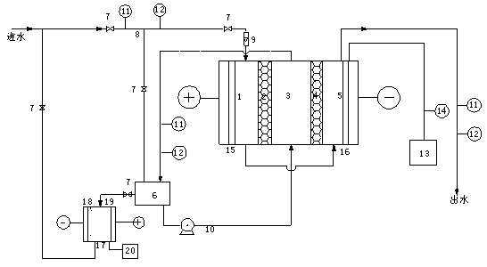
[0029] use figure 1 Shown is a device for recovering waste soluble metal salts and purifying waste water. The anode is a titanium mesh electrode coated with ruthenium, and the cathode is a stainless steel mesh electrode. The anion and cation exchange resins are respectively D201 macroporous strongly basic styrene-based hydrogen-oxygen resin and D001 macroporous styrene-based hydrogen-type resin. The size of the pool is 0.10864m 3 (1.94*0.4*0.14), the thickness of the resin wall is 0.14m. The raw water is the cleaning water of the plated parts discharged from the copper plating production line of the electroplating plant, which contains Cu 2+ About 50mg / L, pH value is about 6; 65V voltage is applied to both ends of the device electrodes; under this operating condition, the raw water treatment capacity is 0.25m 3 / min, Cu in fresh water 2+ The concentration is lower than 0.05mg / L, the current efficiency reaches about 40%, the Cu in concentrated water 2+ After about 10 hou...

Embodiment 2

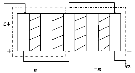
[0031] In embodiment 2, adopt two groups of devices to process in series containing Cu 2+ 100mg / L ( figure 2 ), the deionization principle and operation steps of the devices at all levels are the same as those in Example 1. Apply a voltage of 60V to both ends of the electrode of the device, and run stably and continuously for 480 hours. The concentration of the effluent after the first stage is about 5-10mg / L, and the concentration of the effluent after the second stage is about 0.2-1.0mg / L. The total removal rate can be as high as 99%-99.8%.

Embodiment 3

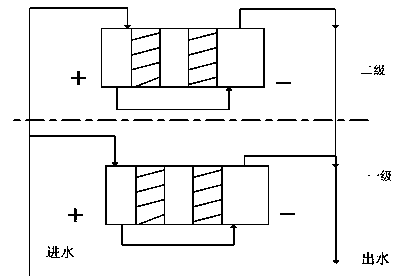
[0033] In embodiment 3, two groups of single-stage devices in embodiment 1 are adopted to process the raw water in parallel to be the plated piece cleaning water discharged from the copper plating production line of the electroplating plant ( image 3 ), which contains Cu 2+ About 50mg / L, pH value about 6; 65V voltage is applied to both ends of the device electrodes; under this operating condition, the raw water treatment capacity is at least doubled to 0.8-0.5m after continuous operation for a week 3 / min, the removal rate of ions can reach more than 98%.


PUM


Abstract

The invention discloses a soluble metal salt recovery and wastewater purification device and a method thereof. The device comprises an anode chamber, a first fresh water tank, a concentrated water tank, a second fresh water tank and a cathode chamber. Each compartment is separated by ion selective permeation walls. Voltages are added at two ends of the device. Influent water first passes through the first fresh water tank, then passes through the second fresh water tank, and finally purified effluent water can be obtained. Under the effect of electromigration, negative and positive ions migrate towards the positive ion and negative ion selective permeation walls, and are adsorbed and then penetrate into the concentrated water tank, inside which the concentrated solution can be used for ion recovery. The device of the invention can be used for pure water preparation, seawater desalination, mineral matter extraction from underground mineral water, boiler water softening, and also can be used for industrial wastewater treatment as well as recovery of useful ions in wastewater.

Description

technical field [0001] The invention relates to a soluble metal salt recovery and waste water purification device and method thereof. Background technique [0002] Compared with ordinary electrodialysis (ED), the ion exchange resin filled in the dilute chamber of electrodeionization (EDI) greatly improves the conductivity between the membranes, strengthens the ion migration from the solution to the membrane surface, and destroys the diffusion layer of the membrane surface. In the "ion-poor" state, the limiting current density and current efficiency are significantly improved. In addition, when the desalination chamber is filled with ion exchange resin, the liquid flow velocity in the desalination chamber is much larger than that in the ordinary ED device, and the resin acts as agitator to promote ion diffusion, improve the hydraulic state, and make the desalination chamber system As the conductivity increases, the limiting current density increases accordingly. Therefore, ...

Claims


Application Information

Patent Timeline
Patent Type & Authority Patents(China)
IPC IPC(8): C02F1/469C02F9/06
Inventor 吴祖成廖文张慧敏许伟
Owner ZHEJIANG UNIV
Learn More