
Conductive particle

A conductive particle and non-conductive technology, applied in the field of conductive particles, can solve problems such as short circuit and difficulty in ensuring conductivity, and achieve the effects of preventing poor conduction, sufficient conductivity, and preventing insufficient insulation

Active Publication Date: 2012-05-23
株式会社力森诺科
View PDF22 Cites 15 Cited by
  • Summary
  • Abstract
  • Description
  • Claims
  • Application Information

AI Technical Summary

Problems solved by technology

[0003] However, in recent years, along with the high-definition of liquid crystal displays, the pitch and area of ​​gold bumps used as circuit electrodes of ICs for driving liquid crystals are becoming narrower, so the following problems may occur: the flow of conductive particles of the anisotropic conductive adhesive short circuit between adjacent circuit electrodes
When the smoothness of the electrode is improved, it tends to be difficult to ensure conductivity with normal conductive particles

Method used


Image

  • Conductive particle
  • Conductive particle
  • Conductive particle

Examples


Embodiment 1

[0115] (1) Preparation of conductive particles

[0116] 10 g of plastic nuclei comprising a copolymer of divinylbenzene and acrylic acid and having an average particle diameter of 3.7 μm with an adjusted degree of crosslinking were prepared. The surface of the plastic core has carboxyl groups. The hardness of the plastic core (compression elastic modulus when the particle diameter is deformed by 20% at 200°C, 20% K value) is 150kgf / mm 2 .

[0117] A 30% by mass polyethyleneimine aqueous solution (manufactured by Wako Pure Chemical Industries, Ltd.) having a molecular weight of 70,000 was diluted to 0.3% by mass with ultrapure water. 10 g of the above-mentioned plastic core was added to 300 mL of this 0.3 mass % polyethylene aqueous solution, and stirred at room temperature for 15 minutes. The plastic nucleus was taken out by filtration using a φ3 μm membrane filter (Millipore, Inc.), and the taken plastic nucleus was added to 300 g of ultrapure water and stirred at room tem...

Embodiment 2

[0129] In the same manner as in Example 1, except that 0.53% by mass of silica particle dispersion (total amount of silica: 1.6 g) was used instead of 0.33% by mass of silica particle dispersion (total amount of silica: 1 g). , Plastic cores (composite particles) with silica particles adsorbed on their surfaces, and conductive particles 2 with nickel films formed on their surfaces were prepared. Furthermore, the anisotropic conductive adhesive film and bonded structure samples were produced by the procedure similar to Example 1 using the obtained electroconductive particle 2.

Embodiment 3

[0131] In the same manner as in Example 1, except that 0.42% by mass of silica particle dispersion (total amount of silica: 1.27 g) was used instead of 0.33% by mass of silica particle dispersion (total amount of silica: 1 g). , and the plastic core (composite particle) on which the silica particles were adsorbed on the surface, and the conductive particle 3 on which the nickel film was formed were produced. Furthermore, the anisotropic conductive adhesive film and bonded structure samples were produced by the procedure similar to Example 1 using the obtained electroconductive particle 3.


PUM

PropertyMeasurementUnit
particle sizeaaaaaaaaaa
thicknessaaaaaaaaaa
thicknessaaaaaaaaaa

Abstract

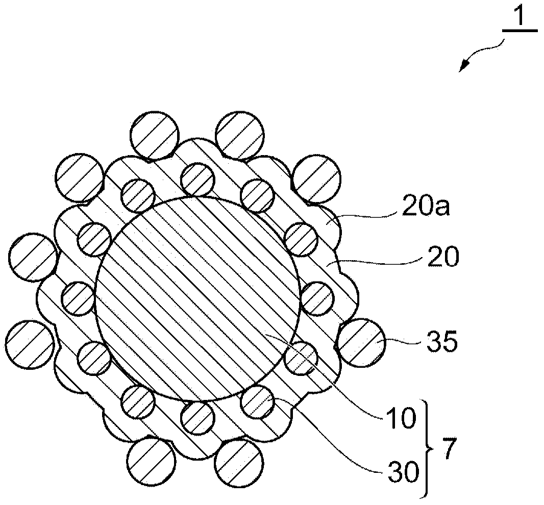
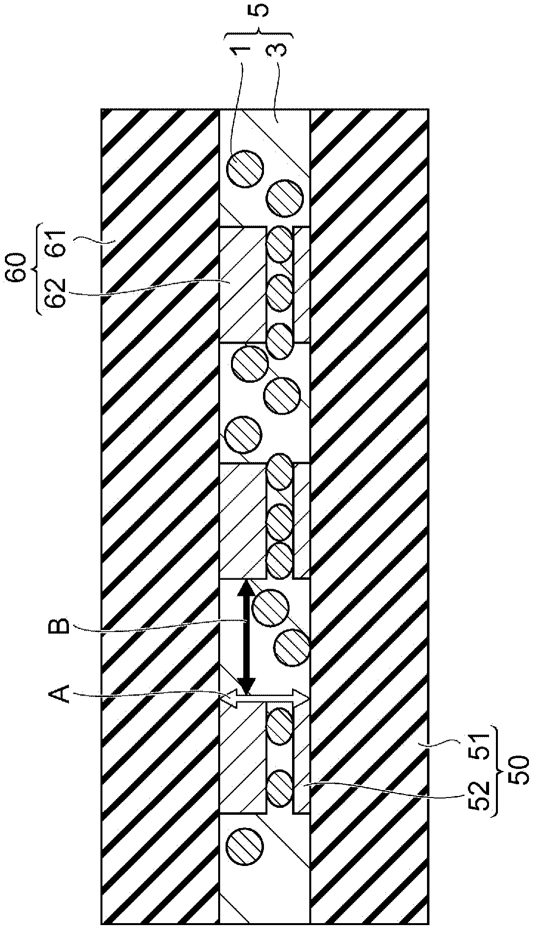
Disclosed is a conductive particle which is capable of achieving sufficient conductivity even when used in an anisotropically conductive adhesive that is used for the purpose of connecting a hard and smooth electrode. Specifically disclosed is a conductive particle (1) which comprises: a composite particle (7) that has a plastic core (10) and non-conductive inorganic particles (30) that are adsorbed on the plastic core (10) by a chemical bond; and a metal plating layer (20) that covers the composite particle (7). The metal plating layer (20) has a surface that is provided with projections (20a), and the non-conductive inorganic particles (30) are harder than the metal plating layer (20).

Description

technical field [0001] The present invention relates to conductive particles suitable for use in anisotropic conductive adhesives. Background technique [0002] There are roughly two methods of mounting liquid crystal drive ICs on glass panels for liquid crystal displays: COG (Chip-on-Glass) mounting and COF (Chip-on-Flex) mounting. In COG mounting, an IC for liquid crystal is directly bonded to a glass panel using an anisotropic conductive adhesive containing conductive particles. On the other hand, in COF mounting, ICs for driving liquid crystals are bonded to flexible tapes having metal wiring, and these are bonded to a glass panel using an anisotropic conductive adhesive containing conductive particles. The term "anisotropy" here means conduction in the pressurized direction and insulation in the non-pressurized direction. [0003] However, in recent years, along with the high-definition of liquid crystal displays, the pitch and area of ​​gold bumps used as circuit ele...

Claims


Application Information

Patent Timeline
Patent Type & Authority Applications(China)
IPC IPC(8): H01R11/01C08J3/12H01B5/00
CPCC09J11/00C08K9/02H01R4/04C09J9/02C08J3/12H01B5/00H01R11/01
Inventor 高井健次赤井邦彦永原忧子松泽光晴
Owner 株式会社力森诺科
Learn More