
Comprehensive polarization measuring device and method of argon fluoride (ArF) laser optical thin film elements

A technology of optical film and measuring device, which is applied in the direction of testing optical properties, etc., can solve the problems of limited measurement accuracy and inaccurate evaluation of polarization characteristics, and achieve the effect of compact structure

Inactive Publication Date: 2013-08-21
CHANGCHUN INST OF OPTICS FINE MECHANICS & PHYSICS CHINESE ACAD OF SCI
View PDF7 Cites 0 Cited by
  • Summary
  • Abstract
  • Description
  • Claims
  • Application Information

AI Technical Summary

Problems solved by technology

Similar to the existing dual optical path spectrometer with polarization optical measurement accessories, the polarization characteristic measurement of this kind of polarization characteristic measurement device only uses a polarizing optical element, and does not use an analyzing optical element in front of the signal light detector. , it is also impossible to accurately evaluate the influence caused by the depolarization effect of optical thin film components, and the measurement accuracy of its polarization characteristics is relatively limited

Method used


Image

  • Comprehensive polarization measuring device and method of argon fluoride (ArF) laser optical thin film elements
  • Comprehensive polarization measuring device and method of argon fluoride (ArF) laser optical thin film elements
  • Comprehensive polarization measuring device and method of argon fluoride (ArF) laser optical thin film elements

Examples


Embodiment

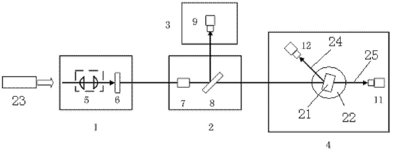
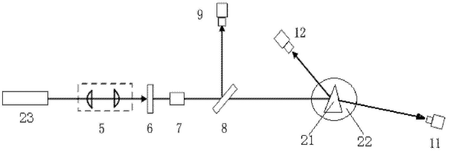
The schematic diagram of the optical path of the integrated polarization measurement device for optical thin film elements of the present invention is as follows figure 2 shown.

refer to figure 1 , which is a structural schematic diagram of the comprehensive polarization measurement device for optical thin film elements of the present invention, the device mainly includes an ArF excimer laser 23, a vacuum cavity pipeline, an ArF excimer laser beam expander collimation device 5, a 193nm polarized light polarizer 7, a polarizer Optical detection device and data acquisition and control system. Wherein the ArF excimer laser 23, the first rectangular vacuum cavity 1, the second rectangular vacuum cavity 2, the third rectangular vacuum cavity 3, the fourth rectangular vacuum cavity 4, the ArF excimer laser beam expanding and collimating device 5, Aperture 6, 193nm polarized light polarizer 7, beam splitter 8, 193nm reference light polarization detection device 9, rotating sample ...


PUM


Abstract

The invention relates to a comprehensive polarization measuring device of argon fluoride (ArF) laser optical thin film elements. An ArF excimer laser, an ArF excimer laser beam expanding and collimating device, an iris diaphragm, a polarizer, a beam splitter and a sample platform of the comprehensive polarization measuring device are placed in sequence along a main optical axis; a reference lightpolarization detecting device is positioned on a reflected light path of the beam splitter; the sample platform is positioned on a transmission light path of the beam splitter; a transmission light polarization measuring device is fixedly mounted on a first rotatable supporting arm; a reflected light polarization detecting device is fixedly mounted on a second rotatable supporting arm; the sampleplatform, the first rotatable supporting arm and the second rotatable supporting arm are positioned in the same plane and are provided with the same rotation center; and the rotation center is positioned on the main optical axis. By adopting the comprehensive polarization measuring device, the polarization reflectivity, the transmissivity, the reflection depolarization ratio and the transmission depolarization ratio of the optical thin film elements in different shapes, which are positioned at different incidence angles, can be measured at the same time, and thereby the need of various ArF laser optical thin film elements on polarization performance assessment can be met to the maximum limit.

Description

technical field [0001] The invention belongs to the technical field of ArF excimer laser application, and relates to a comprehensive polarization measurement device for ArF laser optical film elements. Background technique [0002] Light wave is a kind of transverse wave, and the vibration direction of its light wave vector is perpendicular to the propagation direction of light. According to the change of the vibration direction of the light wave vector, light can be divided into natural light and polarized light, and polarized light can be further divided into plane polarized light (linearly polarized light), circularly polarized light, elliptically polarized light, and partially polarized light. For linearly polarized light, according to the vibration direction of the light wave vector, it can be divided into P polarization and S polarization. The light wave electric vector parallel to the incident plane is P polarization, and the light wave electric vector perpendicular t...

Claims


Application Information

Patent Timeline
Patent Type & Authority Patents(China)
IPC IPC(8): G01M11/02
Inventor 邓文渊金春水靳京城
Owner CHANGCHUN INST OF OPTICS FINE MECHANICS & PHYSICS CHINESE ACAD OF SCI
Learn More