
Semiconductor direct current photoelectric transformer

A semiconductor and transformer technology, applied in the field of current and voltage transformation, can solve the problems of inductive reactance effect, manufacturing difficulty, loss of large electric energy, etc., and achieve the effect of improving light wave transmission efficiency, good insulation characteristics, and high light wave energy transmission efficiency

Active Publication Date: 2012-04-25
郭磊
View PDF5 Cites 13 Cited by
  • Summary
  • Abstract
  • Description
  • Claims
  • Application Information

AI Technical Summary

Problems solved by technology

[0002] In daily applications, traditional power transmission mainly uses alternating current for transmission, mainly because alternating current is easy to transform, easy to realize long-distance power transmission, and low-voltage power distribution and transformation at the user end.
However, the use of AC transmission has great defects: first, the inductive reactance effect generated by alternating current cannot be ignored, especially for high-frequency alternating current, its inductive reactance effect will have a great impact on alternating current; at the same time, due to the existence of skin effect, making The effective area of ​​the AC transmission wire is small, and a large amount of electric energy will be lost in the process of long-distance power transmission
At present, this kind of converter equipment is difficult to manufacture and expensive. Therefore, the application scope of DC power transmission at this stage is mainly limited to long-distance large-capacity power transmission and submarine cable power transmission, which greatly limits the application field of DC power transmission.

Method used


Image

  • Semiconductor direct current photoelectric transformer
  • Semiconductor direct current photoelectric transformer
  • Semiconductor direct current photoelectric transformer

Examples


Embodiment Construction

[0034] Embodiments of the present invention are described in detail below, examples of which are shown in the drawings, wherein the same or similar reference numerals designate the same or similar elements or elements having the same or similar functions throughout. The embodiments described below by referring to the figures are exemplary only for explaining the present invention and should not be construed as limiting the present invention.

[0035] The following disclosure provides many different embodiments or examples for implementing different structures of the present invention. To simplify the disclosure of the present invention, components and arrangements of specific examples are described below. Of course, they are only examples and are not intended to limit the invention. Furthermore, the present invention may repeat reference numerals and / or letters in different instances. This repetition is for simplicity and clarity and does not in itself indicate a relationshi...


PUM


Abstract

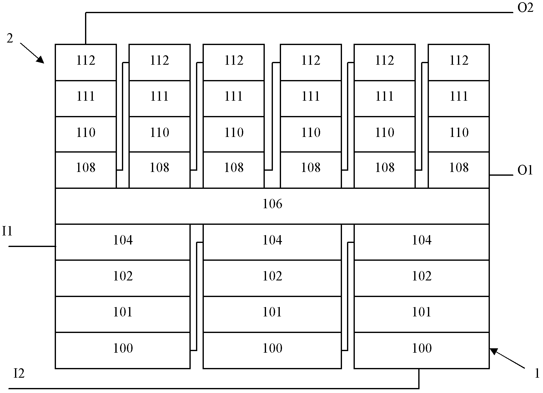
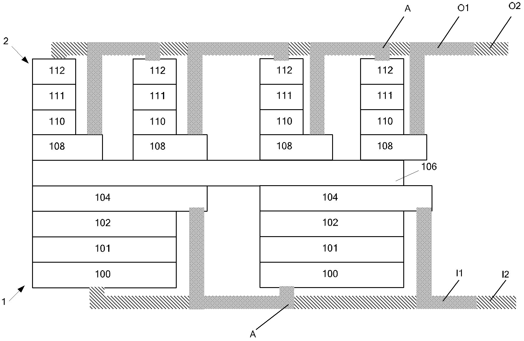
The invention provides a semiconductor direct current photoelectric transformer which comprises an isolating layer, a plurality of electrooptical conversion structures and a plurality of photoelectric conversion structures, wherein the electrooptical conversion structures are formed at one side of the isolating layer; the electrooptical conversion structures are mutually connected in series; eachelectrooptical conversion structure comprises a first electrode layer, an electrooptical conversion layer formed on the first electrode layer and a second electrode layer formed on the electroopticalconversion layer; the photoelectric conversion structures are formed at the other side of the isolating layer; the photoelectric conversion structures are mutually connected in series; each photoelectric conversion structure comprises a third electrode layer, a photoelectric conversion layer formed on the third electrode layer and a fourth electrode layer formed on the photoelectric conversion layer; and the isolating layer, the second electrode layer and the third electrode layer are transparent to working light rays emitted by the electrooptical conversion layer. The semiconductor direct current photoelectric transformer of the embodiment of the invention has the advantages of high-voltage resistance, no electromagnetic radiation, no coil structure, no influence by solar radiation, and the like.

Description

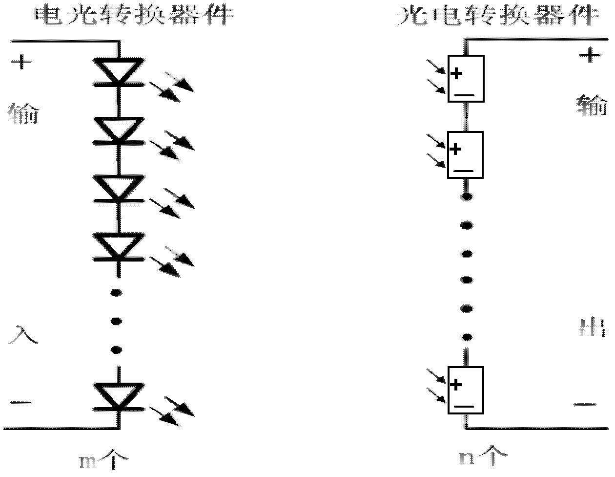
technical field [0001] The invention relates to the field of current and voltage transformation, in particular to a semiconductor DC photoelectric transformer. Background technique [0002] In daily applications, traditional power transmission mainly uses alternating current for transmission, mainly because alternating current is easy to transform, easy to realize long-distance power transmission, and low-voltage power distribution and transformation with users. However, the use of AC transmission has great defects: first, the inductive reactance effect generated by alternating current cannot be ignored, especially for high-frequency alternating current, its inductive reactance effect will have a great impact on alternating current; at the same time, due to the existence of skin effect, making The effective area of ​​the AC transmission wire is small, and a large amount of electric energy will be lost in the process of long-distance power transmission. Secondly, AC transmis...

Claims


Application Information

Patent Timeline
Patent Type & Authority Applications(China)
IPC IPC(8): H01L31/12H01L31/153
Inventor 郭磊
Owner 郭磊
Learn More